
Related Manuals for AUDAC CAP412


Summary of Contents for AUDAC CAP412
-
Page 1: User Manual
CAP412 4 x 100V Power Amplifier AUDAC PROFESSIONAL AUDIO EQUIPMENT CAP412 Four Channel 100V Power Amplifier CAP412 User Manual & Installation Guide... - Page 2 A U D A C P R O F E S S I O N A L A U D I O E Q U I P M E N T User Manual & Installation Guide AUDAC http://www.audac.eu info@audac.eu...
-
Page 3: Table Of Contents
Index INTRODUCTION ............................................. 3 ENVIRONMENT ............................................4 SAFETY REQUIREMENTS ........................................5 CAUTION – SERVICING ........................................5 OVERVIEW FRONT AND REAR PANEL ..................................6 FRONT PANEL OVERVIEW ........................................ 6 REAR PANEL OVERVIEW ........................................7 CONNECTING THE AMPLIFIER ......................................9 INPUT CONNECTIONS ........................................9 CONNECTION STANDARDS ...................................... -
Page 4: Introduction
Introduction This section briefly describes the possibilities of the CAP412 four channel power amplifier. he CAP412 four channel power amplifier was developed as an easy to use, flexible solution for multifunctional use. During the development of the CAP412, the AUDAC-engineers wanted to achieve four goals:... -
Page 5: Environment
Chapter Environment Do not place this unit in an enclosed environment such as a bookshelf or closet. Ensure that there is adequate ventilation to cool the unit. Do not block the ventilation openings. Do not place the unit in environments which contain high levels of dust, heat, moisture or vibration. -
Page 6: Safety Requirements
Only use a grounded socket outlet and a power cord with grounding plug to plug in the unit. This unit is not a toy. It should not be operated by children. Do not stick objects through the openings of the CAP412 Do not open the unit (risk for electrical shock). ... -
Page 7: Overview Front And Rear Panel
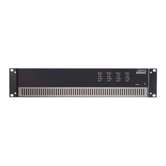
Chapter Overview front and rear panel Front panel overview 2. Indicator LED’s CAP412 1. Power switch Description 1. Power switch: By means of the power switch, the amplifier can be turned ON and OFF. When the amplifier is switched on, the blue LED located next to the power button will illuminate. -
Page 8: Rear Panel Overview
Rear panel overview 3. AC power inlet with fuse 4. High pass filter switch 5. Gain control potentiometer 6. Loudspeaker connections 7. Input connections Description 3. AC Power inlet with fuse: The mains power supply (100~240V AC / 50~60Hz) has to be applied to this AC power inlet. The connection is made by an IEC power connector and is fitted with a fuse. - Page 9 7. Input connections: The input connections of the amplifier are performed using balanced XLR connectors. Every channel has an XLR input connector and a XLR link output connector. The input signal from the signal source, pre-amplifier or mixer should be connected to the XLR input connections. And by means of the XLR link output connectors, the signal can be linked through to multiple amplifiers.
-
Page 10: Connecting The Amplifier
And by means of the XLR link output connectors, the signal can be linked through to multiple amplifiers. Connection standards The in- and output connections of AUDAC audio equipment are performed corresponding to international wiring standards for professional audio equipment. XLR:... -
Page 11: Output Connections
Connect the COM terminal to the negative (-) speaker lead and connect the other suitable terminal to the positive (+) speaker lead. Low impedance applications: When using the CAP412 amplifier in low impedance applications, the loudspeakers should be connected between the “COM” and “4 Ohm” connection terminals. 4 Ω... - Page 12 Constant voltage applications: When using the CAP412 amplifier in constant voltage applications, the loudspeakers should be connected between the “COM” and “100V or “70V” connection terminals. Matching Transformer Matching Transformer Attention Make sure the loudspeakers are always connected on Low impedance outputs OR on Constant voltage outputs, but NEVER use the Low impedance outputs and Constant voltage outputs of the same channel at the same time.
-
Page 13: Block Diagram
Chapter Block Diagram... -
Page 14: Additional Information
Chapter Additional Information Technical specifications CAP412 Performance 8 Ohm 75 Watt Rated power 4 Ohm 120 Watt 100 Volt 120 Watt Input Sensitivity 1.0 Vrms (Balanced / Impedance 10 kOhm) Frequency response (± 1 dB) 50 Hz – 18 kHz Signal to Noise ratio >... -
Page 15: Personal Notes
Personal notes...
Need help?
Do you have a question about the CAP412 and is the answer not in the manual?
Questions and answers