
Related Manuals for AUDAC DPA74


Summary of Contents for AUDAC DPA74
-
Page 1: User Manual
DPA74/154 AUDAC PROFESSIONAL AUDIO EQUIPMENT DPA74/154 Quad Channel Class-D Amplifier User Manual & Installation Guide... - Page 2 A U D A C P R O F E S S I O N A L A U D I O E Q U I P M E N T User Manual & Installation Guide AUDAC http://www.audac.eu info@audac.eu...
-
Page 3: Table Of Contents
Index INTRODUCTION ............................................. 3 ENVIRONMENT ............................................4 SAFETY REQUIREMENTS ........................................5 CAUTION – SERVICING ........................................5 OVERVIEW FRONT AND REAR PANEL ..................................6 FRONT PANEL OVERVIEW ........................................ 6 FRONT PANEL DESCRIPTION ......................................6 REAR PANEL OVERVIEW ........................................7 REAR PANEL DESCRIPTION ......................................7 CONNECTING THE AMPLIFIER ...................................... -
Page 4: Introduction
The small size of a single rack space make them very interesting for fixed rack mount as well as mobile applications. The DPA74 and DPA154 are four channel Class D amplifiers capable of delivering a power up to 4 x 150 Watt., with various specific features and advanced protection circuitry which protects against DC malfunctioning, short circuit, overheating and overload. -
Page 5: Environment
Chapter Environment Do not place this unit in an enclosed environment such as a bookshelf or closet. Ensure that there is adequate ventilation to cool the unit. Do not place the unit in environments which contain high levels of dust, heat, moisture or vibration. -
Page 6: Safety Requirements
Safety Requirements Always handle the unit with care. Only use a grounded socket outlet and a power cord with grounding plug to plug in the unit. This unit is not a toy. It should not be operated by children. Do not stick objects through the openings. Do not open the unit (risk for electrical shock). -
Page 7: Overview Front And Rear Panel
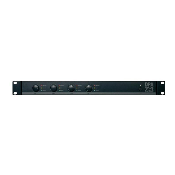
Chapter Overview front and rear panel Front panel overview 2. Gain controls 1. Power Switch 3. Indicator LED’s Description 1. Power switch: By means of the power switch, the amplifier can be turned ON and OFF. When the amplifier is switched on, the blue LED located above the power button will illuminate. -
Page 8: Rear Panel Overview
The connection is made by an IEC power connector and is fitted with a fuse. When replacing the fuse, make sure that the value of the replacement fuse matches the value of the original fuse. (T4AL/250V for DPA74 & T6.3AH/250V for DPA154) 5. Loudspeaker connections: The loudspeaker output connections are performed by means of Euro Terminal Blocks. -
Page 9: Connecting The Amplifier
Chapter Connecting the Amplifier Input connections The input connections of the amplifier should be made by connecting the signal from the signal source, pre-amplifier or mixer to the balanced XLR input connections. Next to every pair of input channel connectors is an operational mode switch provided. By means of this switch, the operational mode of the amplifier can be selected. - Page 10 The signal sources should only be connected to the balanced XLR connectors of Channel 1 and Channel 3. For more information about how the loudspeakers should be connected in bridge mode, refer to the “Output Connections” section of this user manual. 3) Parallel Mode: In parallel mode (Right position of the switch), the amplifier is configured in a way that only the signal applied to the XLR input connector of Channel 1 and Channel...
-
Page 11: Output Connections
Output connections The loudspeaker connections for every output channel are performed with a two pin Euro- Terminal block connector. Stereo Mode: Stereo mode will be the most commonly used operation method for this amplifier. The loudspeakers of each channel can be connected with a separate two-core connection cable to the Euro-Terminal block output connectors. -
Page 12: Connections Standards
Note Do not connect any 100V line transformers to the loudspeaker outputs of the amplifier. Connection standards The in- and output connections of AUDAC audio equipment are performed corresponding to international wiring standards for professional audio equipment. XLR: 1 = ground / shield... -
Page 13: Block Diagram
Chapter Block Diagram... -
Page 14: Additional Information
Chapter Additional Information Technical specifications DPA74 DPA154 Performance Stereo @ 8 Ohm 4 x 50 Watt 4 x 80 Watt Rated power Stereo @ 4 Ohm 4 x 75 Watt 4 x 150 Watt (1 kHz, THD 1%) Bridge @ 8 Ohm... -
Page 15: Personal Notes
Personal notes...
Need help?
Do you have a question about the DPA74 and is the answer not in the manual?
Questions and answers