Sign In
Upload
Download
Table of Contents
Contents
Add to my manuals
Delete from my manuals
Share
URL of this page:
HTML Link:
Bookmark this page
Add
Manual will be automatically added to "My Manuals"
Print this page
×
Bookmark added
×
Added to my manuals
Manuals
Brands
AUDAC Manuals
Amplifier
PMQ240
User manual
AUDAC PMQ240 User Manual
Pmq series. wavedynamics
Hide thumbs
1
Table Of Contents
2
3
4
5
6
7
8
9
10
11
12
13
14
15
16
17
18
19
20
21
22
23
24
25
26
27
28
29
30
31
32
page
of
32
Go
/
32
Contents
Table of Contents
Bookmarks
Table of Contents
User Manual
Table of Contents
Introduction
Precautions
EC Declaration of Conformity
Chapter 1: Pin Connections and Connectors
Chapter 2 : Front & Rear Panel
Front Panel Overview
Front Panel Description
Rear Panel Overview
Rear Panel Description
Quick Start Guide
Chapter 3 : Quick Start Guide
Ready
Chapter 4 : Connecting the Amplifier
Input Connections
Output Connections
Chapter 5: Configuring the Amplifier
Menu Structure Overview
Main Screen
Settings Menu
Level
Input
Mute
Output Setup
Filters
Equalizing
Delay
Max Level
Standby
Limiter
Phase Reverse
Roll off
Output Type
Clear Presets
General Setup
Temperature
Input Gain
Password
Lcd
Usb
Info
Factory Reset
Save
Lock
Chapter 6: Additional Information
Technical Specifications
Notes
Advertisement
Quick Links
1
User Manual
2
Front Panel Overview
3
Input Connections
4
Password
5
Technical Specifications
Download this manual
PMQ Series
User manual
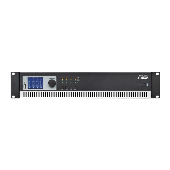
PMQ240 / PMQ480 / PMQ600
www.audac.eu
Table of
Contents
Previous
Page
Next
Page
1
2
3
4
5
Advertisement
Table of Contents
Need help?
Do you have a question about the PMQ240 and is the answer not in the manual?
Ask a question
Questions and answers
Related Manuals for AUDAC PMQ240
Amplifier AUDAC POW2 Installation Manual
Sixteen channel power amplifier (11 pages)
Amplifier AUDAC PRE116 User Manual
6-channel stereo preamplifier (16 pages)
Amplifier AUDAC PRE126 User Manual
6-channel stereo preamplifier (16 pages)
Amplifier AUDAC PX110 User Manual And Installation Manual
Speaker cabinet (6 pages)
Amplifier AUDAC PRE16 User Manual & Installation Manual
6 channel, single/double output zone (32 pages)
Amplifier AUDAC PMQ480 User Manual
Pmq series. wavedynamics (32 pages)
Amplifier AUDAC PMQ600 User Manual
Pmq series. wavedynamics (32 pages)
Amplifier AUDAC PRE220 User Manual
10-channel stereo preamplifiers (16 pages)
Amplifier AUDAC PRE240 User Manual
10-channel stereo preamplifiers (16 pages)
Amplifier AUDAC DPA74 User Manual & Installation Manual
Professional audio equipment quad channel class-d amplifier (15 pages)
Amplifier AUDAC M1 User Manual & Installation Manual
Multimedia amplifier (28 pages)
Amplifier Audac R1 User Manual & Installation Manual
Multi-room amplifier (35 pages)
Amplifier AUDAC DPA73 User Manual & Installation Manual
Triple channel class-d amplifier (16 pages)
Amplifier Audac CAP412 User Manual & Installation Manual
Four channel 100v power amplifier (15 pages)
Amplifier Audac CAP224 User Manual
Cap series professional 100v multi-channel power amplifiers (16 pages)
Amplifier AUDAC R2 User Manual
Multi-zone audio matrix system (60 pages)
This manual is also suitable for:
Pmq480
Pmq600
Table of Contents
Print
Rename the bookmark
Delete bookmark?
Delete from my manuals?
Login
Sign In
OR
Sign in with Facebook
Sign in with Google
Upload manual
Upload from disk
Upload from URL


Need help?
Do you have a question about the PMQ240 and is the answer not in the manual?
Questions and answers