
Related Manuals for AUDAC M1


Summary of Contents for AUDAC M1
-
Page 1: User Manual
Multimedia Amp AUDAC PROFESSIONAL AUDIO EQUIPMENT Multimedia Amplifier M1 User Manual & Installation Guide... - Page 2 A U D A C P R O F E S S I O N A L A U D I O E Q U I P M E N T User Manual & Installation Guide AUDAC http://www.audac.be info@audac.be...
-
Page 3: Table Of Contents
SAFETY REQUIREMENTS ......................................... 5 CAUTION - SERVICING..........................................5 PIN CONNECTIONS ON CONNECTORS....................................6 ATTENTION ..............................................6 OVERVIEW FRONT AND REAR PANEL OF THE M1................................ 7 FRONT:................................................7 REAR: ................................................7 OVERVIEW INPUTS 1-6 (MIC./ST. LINE) ....................................8 INPUT 1-6 (FRONT)............................................. 8 INPUT 1-6 (REAR) ............................................ -
Page 4: Introduction
It has the flexibility of an advanced multi-zone mixer, combined with several digital options. By simply surfing to the webpage, you can get full control of the M1 basic functions. The M1 can be directly plugged into a basic Ethernet LAN network. No extra control software is needed, just a computer (pda, pocket pc, …) and a web browser with the Macromedia Flash Player 6.0 (or... -
Page 5: Environment
Chapter Environment Do not place this unit in an enclosed environment such as a bookshelf or closet. Ensure there is adequate ventilation to cool the unit. Do not block the ventilation openings. Do not place the unit in environments which contain high levels of dust, heat, moisture or vibration. -
Page 6: Safety Requirements
Do not stick objects through the ventilation openings of the M1. Do not open the unit. (risk for electrical shock) The M1 contains several ‘jumpers’ which can be set. These settings may only be done by qualified people. CAUTION - SERVICING This unit contains no user serviceable parts. -
Page 7: Pin Connections On Connectors
The serial data protocol and wiring can be downloaded at www.audac.be/download or can be asked at info@audac.be. ATTENTION The Cat5 cabling must always be ‘straight’. In case of self made cabling, it must be done as described above, to make the system... -
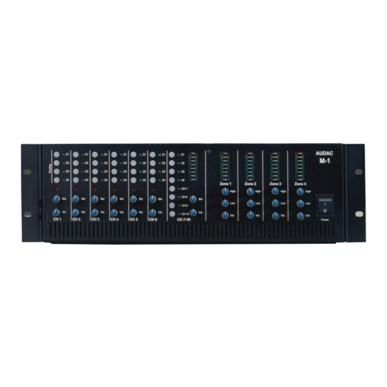
Page 8: Overview Front And Rear Panel Of The M1
Chapter Overview front and rear panel of the M1 FRONT: REAR:... -
Page 9: Overview Inputs 1-6 (Mic./St. Line)
Overview Inputs 1-6 (Mic./St. Line) INPUT 1-6 (FRONT) Routing Buttons + LED: To rout Input to Zone 1-4 Input Clipping LED Input Balance Input Volume INPUT 1-6 (REAR) Dipswitch: Phantom power (+48V) Mic/Line Selection Input Gain 3 band Tone Control Stereo Line Input (Cinch) Microphone Input... -
Page 10: Overview Input 7-10 (4X St. Line)
Overview Input 7-10 (4x St. Line) INPUT 7-10 (FRONT) Input level VU bar (Pre Fader) Routing Buttons + LED Input Selection Ch7-10 Input Balance Input Volume INPUT 7-10 (REAR) Input Gain Adjustment 2 Band Tone Control 4 x Stereo Line Input Ch7-Ch10 (Cinch) -
Page 11: Overview Output Zones
OUTPUT ZONES 1-4 (FRONT) Output Level VU-Bar Two band tone control Zone output volume OUTPUT ZONES 1-4 (REAR) Balanced Line Level Outputs (XLR): 4 Zones Stereo Powered Outputs (Speakon) Amp: 2 x 150W stereo (Not available on the M1 Light) -
Page 12: Overview Data Control Ports
Overview DATA Control Ports DATA CONTROL PART (Rear) Ethernet connection (RJ45) Wall Panel Outlets (RS485) Serial Control Port (RS232) Input Priority settings... -
Page 13: Getting Started
Channel 7-10 has a 2 band tone Control and an input gain adjustment. The output section on the rear panel of the M1 Light has 4 balanced stereo output zones (XLR). The M1 has also two 2 stereo output amplifiers (2x 150W /4Ohms stereo) for Zone outputs 1 and 2 available through Speakon connectors. - Page 14 M1 front panel. Hold down the 2 buttons for a few seconds. The routing buttons (Z1 to Z4) of the input channels on the front panel of the M1 can be disabled by pressing together the ‘ch7’ and ‘ch10’ buttons. Hold down the two buttons for at least 10 seconds !! To enable the routing buttons on the front panel of the M1, press down the ‘ch7’...
-
Page 15: Wire Up The System
Chapter Wire up the System The AUDAC M1 amplifier is very easy in use. Following cable specs must be followed to guarantee a correct operation: 1. Speaker Cable: minimum 2x1.5 mm2 (distance >15m: 2x2.5mm2) 2. Wall Mounted Panel: UTP/FTP Cat5 cable 3. - Page 16 Notebook Pocket Amplifier 1 Ethernet XLR, Left XLR, Right Wireless Amplifier 2 Wall panel 1 XLR, Left XLR, Right Wall panel 2 RS485 Wireless Router RS485 Ethernet Microphone 1 Microphone 2 RS232 Tuner CD player Home automation systems...
-
Page 17: Bridge Mode
In the following paragraphs the proper wiring for a bridged M1 stereo setup is explained. Connect the left output channel of the audio source to the left channel of an input channel of the M1. Connect the right channel of the audio source to the left channel of another input channel of the M1. -
Page 18: Remote Control Interface
Chapter Remote Control Interface To use the remote control interface, the M1 has to be plugged in to an Ethernet LAN network with a standard (straight) network cable. Make sure the M1 default network address (192.168.0.180) is within range of the connected Ethernet LAN network ! If the M1 default network address is not within range of your LAN network, contact your network specialist. -
Page 19: Standard Web Based User Interface
Standard Web Based User Interface LOG-IN SCREEN: When you surf to the webpage of the M1, you will see the logon screen of the M1. Default the IP address is http://192.168.0.180 You will have to enter a user name and password to get access. Default the following words are... -
Page 20: Control Screen
CONTROL SCREEN: If you press “enter” after typing the correct username and password, you get access to the control screen of the M1. After logging in, the “Connection Status” will indicate “online” if a connection with the M1 has been made. -
Page 21: Configuration Screen
CONFIGURATION SCREEN: This window will be opened after pressing the “Configuration” button in the control window. (Default Username: audac, default password: M1) In this window the IP address can be changed and DHCP can be enabled. The user name and password and the administrator name and password can be changed. -
Page 22: Lite Web Based User Interface
The purpose of the Lite Web Based User Interface is to offer easy access to the basic functions of the M1 and to offer access to the M1 on devices with a small screen, e.g. pocket PC’s, PDA’s, GSM’s …... -
Page 23: Room Configuration Screen
To configure another room or to go back to the “ Start-up Screen “, press on the name of the selected room. To change the names of the input sources and/or the rooms, press 3 times the “ Audac “ logo on the bottom of the screen. -
Page 24: Name Configuration Screen
NAME CONFIGURATION SCREEN: This screen can be activated by pressing 3 times on the “Audac” logo in the “Room Configuration Screen”. Here you can change the names of the “ Rooms“ and the names of the “ Input Sources“. By pressing the “... -
Page 25: Wall Mounted Control Panels (Optional)
If the wall mounted control panel is connected to the M1, and the M1 is turned on, the digit on the wall mounted control panel will show a zero for a couple of seconds, for the next couple of seconds it will show the zone output for which the wall mounted control panel is configured and last it will keep displaying the selected input source. -
Page 26: Jumper Settings For Zone Output Selection
Jumper settings for zone output selection A B C D E Zone output J J J J J J J J J J J J J J J J = set jumper... -
Page 27: Additional Information M1
Additional Information M1 Technical specifications Sensitivity Microphone input -60/-20 dB 600 Ohm balanced Line input -20/+4 dB 10k Ohm Frequency response 20 Hz – 20 kHz T.H.D. by 1 kHz less than 0.1% Signal to Noise ratio 90 dB Slew rate +/- 30V/µsec... -
Page 28: Personal Notes
Personal Notes...
Need help?
Do you have a question about the M1 and is the answer not in the manual?
Questions and answers