Table of Contents
Advertisement
Quick Links
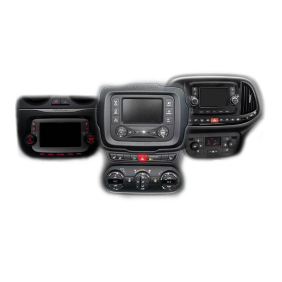
Alfa Romeo, Citroen, Dodge, Fiat and Peugeot vehicles
with Uconnect 5 VP2 / RA2 System
Video-inserter for front- and rear-view camera
Product features
Video-inserter for factory-infotainment systems
1 CVBS Input for rear-view camera
1 CVBS Input for front camera
2 CVBS video-inputs for after-market devices (e.g. USB-Player, DVB-T2 tuner)
Automatic switching to rear-view camera input on engagement of the reverse gear
Automatic front camera switching after reverse gear for 10 seconds
Video-in-motion (ONLY for connected video-sources)
Video-inputs NTSC and PAL compatible
Version 22.10.2020
r.LiNK Video-inserter
CI-UCON5N
Compatible with
and two additional video sources
HW CAM(V100)(V12)
CI-UCON5N
Advertisement
Table of Contents

Related Manuals for Car-Interface.com r.Link CI-UCON5N


Summary of Contents for Car-Interface.com r.Link CI-UCON5N
- Page 1 r.LiNK Video-inserter CI-UCON5N Compatible with Alfa Romeo, Citroen, Dodge, Fiat and Peugeot vehicles with Uconnect 5 VP2 / RA2 System Video-inserter for front- and rear-view camera and two additional video sources Product features Video-inserter for factory-infotainment systems 1 CVBS Input for rear-view camera ...
-
Page 2: Table Of Contents
Contents 1. Prior to installation 1.1. Delivery contents 1.2. Checking the compatibility of vehicle and accessories 1.3. Connectors-video interface 1.4. Settings of the 8 Dip switches (black) 1.4.1. Activating the front camera input 1.4.2. Enabling the interface’s video inputs (dip 2-3) 1.4.3. -
Page 3: Prior To Installation
Legal Information By law, watching moving pictures while driving is prohibited, the driver must not be distracted. We do not accept any liability for material damage or personal injury resulting, directly or indirectly, from installation or operation of this product. Apart from using this product in an unmoved vehicle, it should only be used to display fixed menus or rear-view- camera video when the vehicle is moving (for example the MP3 menu for DVD upgrades). -
Page 4: Checking The Compatibility Of Vehicle And Accessories
1.2. Checking the compatibility of vehicle and accessories Compatibility Brand Compatible vehicles Infotainment systems Alfa Romeo Giulietta, Mito since about 2014 Citroen Jumper since 2014, Relay 2014 Uconnect 5 VP2/RA2 with CD- RAM 1500/2500/3500 since model year 2013 drive and DIN-shell behind Dodge and other models with front-panel... -
Page 5: Connectors-Video Interface
1.3. Connectors - Video-Interface The video-interface converts the connected after-market sources video signals into an RGB digital signal which is inserted in the factory monitor using separate trigger options and it reads vehicle’s digital signals out of the vehicle’s CAN-bus and converts them for the video interface. -
Page 6: Activating The Front Camera Input
1.4.1. Activating the front camera input (dip 1) If set to ON, the interface switches for 10 seconds from the rear-view camera to the front camera input after having disengaged the reverse gear. In addition, a manual switch-over to the front camera input is possible via keypad (short press) from any image mode. Description of the power supply output: see chapter “Power supply output”. -
Page 7: Installation
2. Installation Switch off the ignition and disconnect the vehicle’s battery! The interface needs a permanent 12V source. If -according to factory rules- a disconnection of the battery has to be avoided, it should be sufficient to use the vehicle’s sleep-mode. In case, the sleep-mode doesn’t succeed, the battery has to be disconnected with a resistor lead. -
Page 8: Connection Schema
2.2. Connection schema Version 22.10.2020 HW CAM(V100)(V12) CI-UCON5N... -
Page 9: Connection To The Head-Unit - Lvds
2.3. Connections to the head-unit - LVDS Remove the head-unit and further remove the original housing base plate, which is fixed to the head-unit housing by 4 Torx screws (T9). Clip out the head-unit housing at the head-unit control panel and fold it to the side, like shown in the picture above. - Page 10 Clip out the original 40pin ribbon cable which is connected at the head-unit’s ribbon cable base and connect it to the lower free ribbon cable base “Lcd OUT”of the daughter PCB. (heed the following warning notes!) Note: Due to the very short length of the ribbon cable, there’s only limited space for mounting available.
-
Page 11: Exception Fot Chrysler Vehicles
2.3.1. Exception for Chrysler vehicles In Chrysler vehicles, the ribbon cable connection takes place at the daughter PCB’s upper ribbon cable base „CHRYSLER USES“ (see illustration beside). For that, the daughter PCB first has to be removed from the Exchange housig base plate. -
Page 12: Head Unit - Frame Customizing
2.4. Head unit – frame customizing To reinstall the head-unit’s DIN housing with the daughter PCB below, in most cases a modification of the vehicle’s head unit frame is reqired. For that, the sheet metal plate between the red marked lines has to be cut away, like shown in the following picture. 2.5. -
Page 13: Connection - Pnp Quadlock Harness
2.6. Connection – PNP Quadlock harness Connect the Power/CAN cable’s female 10pin connector to the male 10pin connector of the video-interface. Disconnect the female Quadlock connector of the vehicle harness from the rear of the head-unit and connect it to the male Quadlock connector of the PNP Quadlock harness. - Page 14 2.7. Analog power supply If, after connecting the 20-Pin PNP harness, no interface LED lightens up while the ignition is turned on, the single purple coloured wire Manual ACC of the 12pin interface cable has to be connected additionately to +12V S-contact terminal 86s (e.g.
-
Page 15: Power Supply Output
2.8. Power supply output The red power supply output ACC/front cam out 12V (max 3A) can be used to power an external source and has a different assignment depending on the position of dip switch 1 (of the black 8 dips): Function Dip 1 ON +12V (max. -
Page 16: Connection - Video Sources
2.9. Connecting Video sources It is possible to connect an after-market rear-view camera, an after-market front camera and two more video sources to the video-interface. Before the final installation, we recommend a test-run to detect a incompatibility of vehicle and interface. Due to changes in the production of the vehicle manufacturer there’s always a possibility of incompatibility. -
Page 17: Audio-Insertion
2.9.1. Audio-insertion This interface is only able to insert video signals into the factory infotainment. If an AV- source is connected, the audio insertion has to be done by the factory audio AUX input or an FM-modulator. The inserted video-signal can be activated simultaneously to each audio- mode of the factory infotainment. -
Page 18: After-Market Rear-View Camera
2.9.3. After-market rear-view camera Some vehicles have a different reverse gear code on the CAN-bus which the video-interface is not compatible with. Therefore, there are two different ways of installation. If the video interface receives a signal of the reverse gear, the green wire “Reverse-OUT” of the 20pin cable should carry +12V while the reverse gear is engaged. - Page 19 2.9.3.2. Case 2: Interface does not receive any reverse gear signal If the video interface does not deliver +12V on the green wire of the 20pin cable when reverse gear is engaged (not all vehicles are compatible), an external switching signal from the reverse gear light is required.
-
Page 20: Connection - External Keypad
2.10. Connection - external keypad Connect the keypad’s female 4pin connector to the 12pin interface cable’s male 4pin connector. Note: Even if the switching through several video sources by the keypad mightn’t be required, the keypad’s invisible connection and availability is strongly recommended. Version 22.10.2020 HW CAM(V100)(V12) CI-UCON5N... -
Page 21: Interface Operation
3. Interface operation The interface’s external keypad can be used to switch the enabled inputs. Long press of keypad (2-3 seconds) By long pressing the external keypad (2-3 seconds), the video interfaces witches the input from the factory video to the inserted video sources. Each press (approx. -
Page 22: Specifications
3.1. Picture settings The picture settings can be adjusted by the 3 buttons on the video-interface. Press the MENU button to open the OSD settings menu. To switch to the next menu item, pressing DOWN will change the selected value. The buttons are embedded in the housing to avoid accidental changes during or after installation. -
Page 23: Faq - Trouble Shooting
FAQ – Trouble shooting Interface functions For any troubles which may occur, check the following table for a solution before requesting support from your vendor. Symptom Reason Possible solution Not all connectors have been reconnected to factory head- Connect missing connectors. unit or monitor after installation. - Page 24 Symptom Reason Possible solution Camera input picture Use relay or electronics to "clean" reverse gear lamp black. Camera power taken directly power. Alternatively, if CAN-bus box is compatible Camera input picture from reverse gear lamp. with the vehicle, camera power can be taken from green wire of 6pin to 8pin cable.
Need help?
Do you have a question about the r.Link CI-UCON5N and is the answer not in the manual?
Questions and answers