Table of Contents
Advertisement
Quick Links
with NBT2 and 6.5, 7, 8.8 and 10.25inch monitor and HSD+2 plug
with NBT2 8.8inch monitor and HSD+2 plug
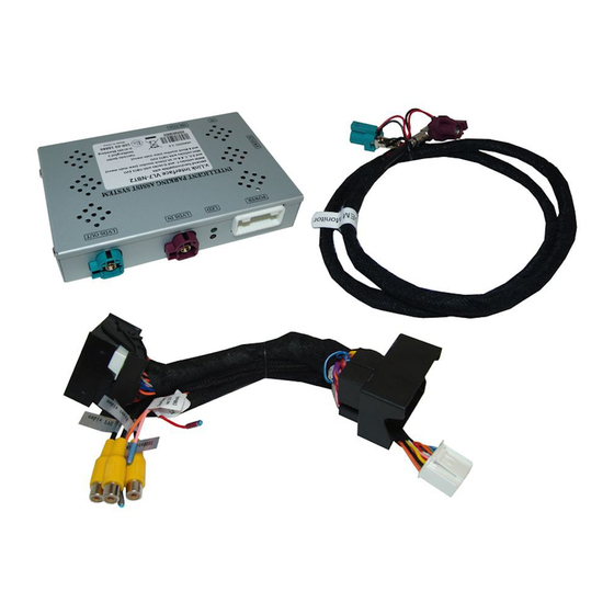
Video-inserter for one rear-view camera, one front camera
Product features
Video-inserter for factory-infotainment systems
CVBS Input for one rear-view camera
CVBS Input for one front camera
1 CVBS Video-input for after-market Video sources (e.g. USB-Player, DVB-T2 Tuner)
Automatic switching to rear-view camera input on engagement of the reverse gear
Automatic front camera switching after disengaging reverse gear for 10 seconds
Dynamic parking guide lines for rear-view camera (not available for all vehicles)
Video-in-motion (ONLY for connected video-sources)
Video-inputs NTSC compatible
Version 08.04.2021
v.LiNK Video inserter
CI-VL7-NBT2
Compatible with
BMW
vehicles F-and G-series
Mini
vehicles
and one additional video input
HW: 1.8/1.9
CI-VL7-NBT2
Advertisement
Table of Contents

Related Manuals for Car-Interface.com v.link CI-VL7-NBT2


Summary of Contents for Car-Interface.com v.link CI-VL7-NBT2
- Page 1 v.LiNK Video inserter CI-VL7-NBT2 Compatible with vehicles F-and G-series with NBT2 and 6.5, 7, 8.8 and 10.25inch monitor and HSD+2 plug Mini vehicles with NBT2 8.8inch monitor and HSD+2 plug Video-inserter for one rear-view camera, one front camera and one additional video input Product features ...
-
Page 2: Table Of Contents
Contents 1. Prior to installation 1.1. Delivery contents 1.2. Checking the compatibility of vehicle and accessories 1.3. Connectors – video interface 1.4. Settings of the 8 Dip switches 1.4.1. Settings – dips1-3 1.4.2. Settings – dips4-8 1.4.2.1. Deviating dip-switch combinations for manual switching to after-market camera (not via CAN-BUS) 1.4.3. -
Page 3: Prior To Installation
Legal Information By law, watching moving pictures while driving is prohibited, the driver must not be distracted. We do not accept any liability for material damage or personal injury resulting, directly or indirectly, from installation or operation of this product. Apart from using this product in an unmoved vehicle, it should only be used to display fixed menus or rear-view- camera video when the vehicle is moving (for example the MP3 menu for DVD upgrades). -
Page 4: Checking The Compatibility Of Vehicle And Accessories
1.2. Checking the compatibility of vehicle and accessories Requirements Brand Compatible vehicles Compatible systems Radios, S606A Business Navigation, S6UNA Navigation, S6U2A Live Cockpit Plus, S609A Professional Navigation, F-series vehicles from about 05/2016 S6UPA Navigation Plus - NBT2 EVO with 6.5, 7, 8.8 and and G-series vehicles with NBT2 10.25 inch monitor (new main menu + more flat iDrive) -
Page 5: Connectors - Video Interface
1.3. Connectors – video interface The video-interface converts the video signals of connected after-market sources in a factory monitor compatible picture signal which is inserted in the factory monitor, by using separate trigger options. Further it reads the vehicle’s digital signals out of the vehicle’s CAN-bus and converts them for the video interface. -
Page 6: Settings - Dips1-3
1.4.1. Settings - dips1-3 Dip switches 1 to 3 are used for basic adjustment for the compatible vehicle types and monitor sizes (make settings according to the table). vehicle - and monitor selection Dip-1 DIP-2 Dip-3 1, 2, 3, 4 series, X3, X4 with 8.8inch monitor OFF ↑... -
Page 7: Explanation Of The Individual Dipswitch Functions
1.4.3. Explanation of the individual dipswitch functions 1.4.3.1. Vehicle and monitor selection (Dip1-3) Dip switches 1 to 3 are used for basic adjustment for the compatible vehicle types and monitor sizes (make settings according to the table). 1.4.3.2. Activating the factory PDC display (Dip-4) Dip 4 is used to activate the factory PDC display (if available) when retrofitting an after-market rear view camera. -
Page 8: Rear View Camera Settings (Dip 8)
1.4.3.5. Rear-view camera settings (Dip 8) Dip 8 is used to set the type of rear view camera. Dip switch position ON switches the interface to factory picture of an existing factory rear view camera as long as reverse gear is engaged. -
Page 9: Connection Schema
2.2. Connection schema Version 08.04.2021 HW: 1.8/1.9 CI-VL7-NBT2... -
Page 10: Connection To Factory Head-Unit And Monitor
2.3. Connections to factory head-unit and monitor 2.3.1. Connection - picture signal cable Disconnect the factory picture signal cable’s bordeaux coloured HSD+2 connector from the rear-side of the monitor and connect it to the bordeaux coloured HSD+2 connector „LVDS IN“ of the video interface . -
Page 11: Special Case - Space Problems With The Monitor Connection
2.3.1.1. Special case - space problems with the monitor connection The picture signal cable’s connecting direction doesn’t have an impact on the system’s function, so that the angled and not-angled HSD+2 connectors are allowed to be interchanged, depending on the HSD+2 connectors mounting space. Disconnect the factory picture signal cable’s bordeaux coloured HSD+2 connector at the rear-side of the monitor and connect it to the bordeaux coloured HSD+2 connector „LVDS IN“... -
Page 12: Connection - Quadlock/Can
2.4. Connection – Quadlock/CAN Connect the female 20pin connector of the 20pin interface cable to the 20pin connector of the video interface. Remove the female 40pin Quadlock connector of the vehicle harness from the rear-side of the head-unit and connect it to the male 40pin Quadlock connector of the 40pin PNP section. -
Page 13: Connection - Video-Sources
2.5. Connection - video sources It is possible to connect an after-market rear-view camera, an after-market front camera and one more after-market video source to the video-interface. Before a final installation of the video sources, we recommend a test-run to ensure the compatibility of vehicle and interface. -
Page 14: Audio Insertion
2.5.1. Audio-insertion This interface is only able to insert video signals into the factory infotainment. If an AV- source is connected, the audio insertion has to be done by the factory audio AUX input or an FM-modulator. The inserted video-signal can be activated simultaneously to each audio- mode of the factory infotainment. -
Page 15: After-Market Rear-View Camera
2.5.3. After-market rear-view camera Some vehicles have a different reverse gear code on the CAN-bus which the video-interface is not compatible with. Therefore, there are two different ways of installation Note: Do not forget to set video interface’s dip8 to OFF before testing. 2.5.3.1. -
Page 16: Case 2: Interface Does Not Receive The Reverse Gear Signal
2.5.3.2. Case 2: Interface does not receive the reverse gear signal If the video interface does not deliver +12V on the green wire of the 12pin cable when reverse gear is engaged (not all vehicles are compatible), an external switching signal from the reverse gear light is required. -
Page 17: Power Supply Output
2.5.4. Power supply output The red power supply output „ACC out +12V“ can be used to power an after-market video source (e.g. USB-player, DVB-T2 tuner). Picture settings in the menu To enter the menu, the front or rear camera image must be shown on the display. Press the cursor to the left. -
Page 18: Adjusting The Dynamic Guide Lines
2.6. Adjusting the dynamic guide lines The display of the dynamic guide lines does not work in all vehicles. The adjustment of the dynamic guide lines does not work in all vehicles where the lines are displayed. Note: During the adjustment of guide lines, Dip-6 must be set to ON. To adjust the guide lines,the reverse gear must be engaged. -
Page 19: Interface Operation
3. Interface operation The factory i-Drive button can be used to manually switch to an after-market video source, activated on the interface (e.g. USB-player, DVB-T2 tuner). Pressing the Menu button on the i-Drive for 2 seconds, switches the input from the factory video to the video source that has been inserted in the interface. -
Page 20: Specifications
4. Specifications BATT/ACC range 9V – 16V Stand-by power drain Power 450mA @12V Video input formats NTSC Temperature range -20°C to +70°C Dimensions Interface box 130 x 88 x 25 mm (W x D x H) 10R-05 16886 Made in China Version 08.04.2021 HW: 1.8/1.9 CI-VL7-NBT2...
Need help?
Do you have a question about the v.link CI-VL7-NBT2 and is the answer not in the manual?
Questions and answers