Table of Contents
Advertisement
Quick Links
Save theSe inStructionS
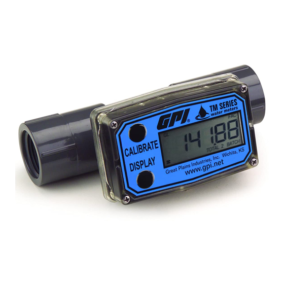
Tm Series Electronic Water meters
User Manual
TM Meter with Computer Display
TABLE OF CONTENTS
English ...........................................................1
Español ..........................................................9
Deutsch .......................................................16
Italiano .........................................................23
Français .......................................................30
ImpOrTANT NOTICE
Use TM Series meters with water and other
chemicals compatible with wetted components
(see Specifications Section). Do not use to meter
fuel or incompatible chemicals. TM Series meters
are available with either a computer for local
electronic display, or a conditioned signal output
module to provide a digital signal to customer
interfacing equipment. TM Series meters with
computer display measure in gallons or litres.
Refer to the Calibration Section for details.
These meters are not legal for trade applications.
TM Series meters are very sensitive to electric
noise if operated within 1 to 2 inches of some
electric motors or other sources of electronic
noise.
04/13
0.544.2843
ENGLISH
www.calcert.com
15
10
20
5
25
0
30
TM Digital Pulse Meter
INSTALLATION
Connections
Install your meter in-line either horizontally or
vertically or at the end of the hose adjacent to
the nozzle. Installation to metal connections is
not recommended. Install as follows:
1. Plan to install turbine with a minimum straight
pipe length as follows:
• Upstream from the turbine, allow a mini-
mum straight pipe length of 10 times the
internal diameter of the turbine.
• Downstream from the turbine, allow a
minimum straight pipe length of 5 times
the internal diameter of the turbine.
2. For Spigot (Pipe) End use only primer and
solvents approved for PVC gluing.
Cut to Length The meter housing can be
shortened by the customer. Each meter has
a "dotted" line feature molded on the top
surface of the housing tube. The housing
can be cut up to this line without harming
any internals.
Most glue on fittings will fit without interfering
with the computer display area. However,
the customer should check all parts before
attempting cut.
Rev. A 920861-01
sales@calcert.
Advertisement
Table of Contents

Related Manuals for GPI TM Series


Summary of Contents for GPI TM Series
- Page 1 ImpOrTANT NOTICE • Downstream from the turbine, allow a minimum straight pipe length of 5 times Use TM Series meters with water and other the internal diameter of the turbine. chemicals compatible with wetted components (see Specifications Section). Do not use to meter 2.
- Page 2 For NPT Fittings wrap all connections with WARNING 3 to 4 wraps of thread tape. Make sure the Compatibility of this product’s material and tape does not intrude into the flow path. the process fluid and/or environment should 3. Attach meter with arrow pointed in the direc- be considered prior to putting into service.
-
Page 3: Square Wave Output
Wiring Diagram 2 SQUARE WAVE OUTPUT 6 volt Square White Wave Signal Terminal Block Customer Interfacing Equipment Black Common (Ground) The terminal block is identified as follows: Pin #1 6 volt square wave Pin #2 +9 to 35 volt DC Input (not used) Pin #3 Common Ground Pin #4 Open Collector signal Output (not used) Conditioned Signal Output... -
Page 4: Operation
1. Remove the four Phillips-head screws from Press the DISPLAY button briefly to switch the front of the module and lift the module between the TOTAL 1, TOTAL 2 BATCH and from the turbine. FLOWRATE. Press DISPLAY briefly to display the TOTAL 2 BATCH. - Page 5 Make sure you meet the meter’s minimum flowrate and selectable – the entered correction will requirements: be applied to all enabled units. TM Series Meters 5. To return to factory calibration (FAC), press and hold both CALIBRATE and DISPLAY 3 inch meter 30 GPM (113.6 LPM)
-
Page 6: Maintenance
CAUTION mAINTENANCE Batteries should ONLY be replaced with Proper handling and care will extend the life and P/N 113520-1 Kit (Includes two each P/N service of the meter. 902004-2 Batteries). Do not mix old with new. Do not use other brands or technologies. Turbine Rotor The meter is virtually maintenance-free. -
Page 7: Specifications
Operating Temperature: +32° to +140° F SpECIFICATIONS (Do not allow fluid to freeze inside meter.) Inlet and Outlet: Battery Life: 5 years Spigot (Pipe) End Models: Storage Temperature: –40° to +158° F TM300/TM300-P 3 inch Schd. 80, Product Weight - lbs.: Spigot (Pipe) Spigot ANSI... -
Page 8: Weee Directive
CAUTION pArTS Do not return the meter without specific The following replacement parts and accessories authority from the GPI Customer Service are available for the TM Series meters: Department. Due to strict regulations governing transportation, handling, and Part No. Description...
Need help?
Do you have a question about the TM Series and is the answer not in the manual?
Questions and answers