Table of Contents

Related Manuals for Stryker SmartPump Rx


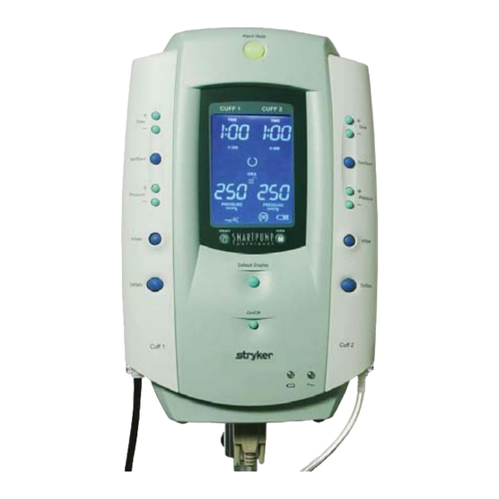
Summary of Contents for Stryker SmartPump Rx
- Page 1 ® SmartPump Tourniquet System Dual Channel Tourniquet Pump REF 5920-011-000 Instructions For Use US Patents 6,051,016; 6,475,228; 6,605,103 Software Version 1.3x Additional US and foreign patents pending 2007/04 5920-011-700 Rev - www.stryker.com...
-
Page 2: Table Of Contents
Table of Contents User/Patient Safety Indications Contraindications Possible Adverse Effects Precautions for Use Environment and Placement 1 Introduction System Overview Features Convenient Preparation Ease of Operation Continuous, Real-time Monitoring Accessory Information* Power Options AC Power Internal Battery Low Battery Power Alarms Maintaining Internal Battery Charge 2 Control Panel and Display Control Buttons... - Page 3 3 Preparing for Use Mounting the SmartPump Power Requirements Initial Set-up Default Parameters Procedure Timer Target Pressure Changing Default Time and Pressure Settings 4 General Use Procedure Connect the Cuff To Fill Line Connector Turn On the SmartPump Setting Timer and Target Pressure Time Display Format Alarm Volume Adjustment Default Display Viewing Preferences...
- Page 4 5 Cleaning and Maintenance Cleaning Recommendations Periodic Maintenance Annual Maintenance Checklist 6 Service Code Summary 7 Specifications...
-
Page 5: User/Patient Safety
This manual explains how to use the Stryker SmartPump ourniquet system. Failure to follow the conditions of use set forth below shall absolve Stryker from any responsibility for the safety, reliability, and performance of this equipment: ♦ Federal law restricts the sale of this device. It may be sold only by or on the order of a physician. -
Page 6: Contraindications
A tourniquet is not suitable for ligatures or cauterization to stop hemorrhages and should never be applied without consideration of the local anatomy. The Stryker SmartPump and associated tourniquet cuff is contraindicated for use on the torso. Tourniquets are contraindicated for use on patients exhibiting unusual or... -
Page 7: Precautions For Use
Ensure power cord is away from personnel traffic and areas of water or liquids. ♦ DO NOT place the SmartPump on an unstable cart, stand, or table. Recommend using the Stryker Roll Stand with pole REF 5920-013-000. ♦ DO NOT use this equipment in the presence of a mixture consisting of flammable anesthetic and air or oxygen or nitrous oxide. -
Page 8: Introduction
‘Main Cuff’ and Cuff 2 as the ‘Second Cuff.’ The SmartPump is shown with the recommended Stryker roll stand and cuff basket. The optional printer, printer tray and power cord organizer mounted below the basket are also shown. Control Panel and Display... -
Page 9: Features
‘OFF(standby)’ and unplugged, the internal battery is kept charged for up to 30 days. ♦ The SmartPump is center mounted to its recommended Stryker roll stand with pole. ♦ Fill lines are attached to the positive locking connectors located at the bottom corners of the SmartPump. -
Page 10: Power Options
Power Options AC Power The Smart Pump’s primary power source is AC power. As a safety feature, the SmartPump’s internal battery provides an alterative (back up) power source if AC power is lost. Always connect the SmartPump to an AC power source for normal operation. -
Page 11: Low Battery Power Alarms
Low Battery Power Alarms If a ‘low battery’ alarm condition occurs, connect the SmartPump to AC power as soon as possible. If AC power is unavailable and the internal battery becomes fully discharged, the SmartPump will maintain cuff pressure. Manual cuff deflation is required. •... -
Page 12: Control Panel And Display
2 Control Panel and Display This section reviews the SmartPump’s interfaces, control panel layout, display screen functions, and icons. The control panel is the user’s interface to control, adjust, and set the following: Procedure Timer and Cuff Pressure, Inflation, Deflation, and Default Display. -
Page 13: Control Buttons
Control Buttons Button Explanation ♦ Turn ON by pressing, then releasing the ON/OFF (standby) button. ♦ Turn OFF by pressing and holding the ON/OFF (standby) button for 1.5 seconds (safety pause). WARNING: Turning OFF the SmartPump while cuffs are inflated will deflate the cuffs and total elapsed time information will be lost. - Page 14 Press and hold the Deflate button for 1.5 seconds (safety pause) DEFLATE to initiate deflation. When deflation begins and after it is completed, the Deflation icon appears next to the cuff pressure gauge. The tourniquet time monitor will stop accumulating time and display the total inflated ‘cuff time.’...
-
Page 15: Display Screen
Display Screen Areas of the SmartPump display screen are illustrated below. Active Cuff Ready Cuff Cuff 1 Cuff 2 Inflation Timer: Default Settings: Indicating elapsed Time: 1 hour time: 50 minutes Pressure: 250 mmHg (Time displayed in hours and minutes format) Pressure Gauge: System Ready... -
Page 16: Display Indicators
Service Required: When the SmartPump detects a condition that requires service, a service code with a wrench is displayed on the LCD and an audible alarm will occur. Note the code and call Stryker for assistance: 1-800-253-3210. Caution: When an alarm is detected, the ‘Alert’ triangle is displayed, and either the time or pressure value will blink. -
Page 17: Preparing For Use
3 Preparing for Use Mounting the SmartPump WARNING: Ensure the SmartPump is mounted on the roll stand pole securely. Failure to comply may result in user/patient injury. Cuff 2 Roll Stand Pole Assemble roll stand. See instructions for use supplied with roll stand. -
Page 18: Power Requirements
Power Requirements The hospital-grade power cord shipped with the SmartPump is UL listed and configured for North American power sources. The SmartPump is configured for use with 120V, 10A, 60 Hz AC power. Initial Set-up The SmartPump is shipped with a fully charged battery, which provides a safety back up power source. -
Page 19: Default Parameters
Default Parameters SmartPump factory preset default time and pressure settings are: Elapsed Procedure Time: One hour 1:00 (Displayed as: Target Cuff Pressure: 250 mmHg (Displayed as: Procedure Timer The timer display shows elapsed procedure time. The timer may be set to the desired cuff inflation time from a minimum of one minute. -
Page 20: Changing Default Time And Pressure Settings
Changing Default Time and Pressure Settings To change the Default Time and/or Target Pressure: If the unit is turned off, press the ON/OFF (standby) button to turn it on. Following self-test, it will enter the ‘Ready’ state. Press the Set/Save button on the side requiring change. The corresponding time and pressure values will blink. -
Page 21: General Use Procedure
4 General Use Procedure The basic steps required to initiate the inflation and deflation of a tourniquet cuff are summarized below: : Prior to cuff inflation, the slight impeding affect caused by the presence of the un-inflated cuff and limb protection sleeve may inhibit venous return, causing slight intraoperative bleeding at the beginning of the procedure. -
Page 22: Turn On The Smartpump
“wrench” icon will appear next to the service code, indicating service is required. DO NOT proceed until you resolve the alarm condition. Failure to comply may result in patient injury. Note the code and call Stryker for assistance: 1-800-253-3210. General Use Procedure... -
Page 23: Setting Timer And Target Pressure
Setting Timer and Target Pressure To adjust the cuff inflation timer or the target pressure, follow the instructions below. Newly set values will remain in effect until they are: (1) changed, (2) the Default Display button is pressed after deflation or, (3) the unit is turned off and restarted. -
Page 24: Time Display Format
Time Display Format Change the Time Display format by pressing both Time (+) buttons simultaneously while the SmartPump is in the ‘ready’ mode, with both cuffs deflated (not active). It is not possible to change the time format if a procedure is started. If it is currently displaying H: MM (hours and minutes) it will automatically shift to Minutes and vice versa. -
Page 25: Default Display Viewing Preferences
Default Display Viewing Preferences The SmartPump is preset to display each cuff default time and pressure setting continuously while in the ‘ready’ mode. When a single cuff is inflated, the other cuff’s default settings remain displayed. In a clinical environment, where single cuff procedures are predominant, the user may choose to ‘minimize’... -
Page 26: Setting Time And Date
Setting Time and Date The SmartPump’s real-time clock tracks Time and Date. Time/Date is maintained by its internal battery. NOTE: The real-time clock does not automatically adjust for daylight savings time changes. To adjust Time and Date, the SmartPump must be in the ‘ready’ mode without an inflated cuff. - Page 27 Set the hours: Use the left side time increase (+) or decrease (-) buttons to adjust the hours setting. Press Set/Save button to save the new hours setting. The minutes will blink. For example, the minute’s value is 34. 12:34 Adjust minutes: Use the left side time increase (+) or decrease (-) buttons to adjust the minutes setting.
-
Page 28: Cuff Inflation
Cuff Inflation The individual channels for Cuff 1 and Cuff 2 operate independently. The SmartPump display screen displays real-time pressure values and total elapsed cuff inflation time for each cuff. Intravenous Regional Anesthesia (IVRA) Lock The Intravenous Regional Anesthesia (IVRA) Lock may be activated either prior to or after inflation. -
Page 29: Cuff Pressure Gauge
Cuff Pressure Gauge The pressure gauge displays the actual pressure in relation to the target pressure. Target pressure has been reached when the wide oval “mushroom” in the center of the gauge is illuminated. Pressure gauge illustrations below depict various states of target pressure. Under Target Target Pressure Over Target... - Page 30 When the Target Time Is Reached Once the inflation timer has reached the target time set for the procedure, the following happens: The Alarm Indicator Mute button flashes red, the ‘Time’ setting on the LCD blinks once per second and an audible alarm chimes 6 times –...
- Page 31 Real-time Pressure Management and Alarms The SmartPump maintains real-time cuff pressure within its normal operating parameters relative to the set target pressure automatically. Pressure variances are typically detected and corrected to the target pressure instantaneously, within two/tenths of a second. Its pressure adjustment responses are sequenced to deliver optimal, progressive pressure compensation without causing overpressure fluctuations, unnecessary - frequent pressure adjustments or triggering false, transient pressure alarms.
- Page 32 WARNING: Cuff and fill line leaks may cause regular, frequent cycling of valves accompanied by repeated or continuous pump motor activity refilling the internal pressure reservoir. This type of leak becomes problematic if the leak volume increases during the procedure, creating a leak rate, which cannot be compensated for by the SmartPump’s maximum flow rate.
-
Page 33: Cuff Deflation
Cuff Deflation A cuff may be deflated at any time during a procedure. To deflate a cuff: ♦ Press the Deflate button for the selected cuff for 1.5 seconds. As the cuff deflates, the following happens: ♦ The numeric pressure and gauge indicate a real-time pressure decrease. -
Page 34: Tourniquet Report Printer
Tourniquet Report Printer When connected to the optional SmartPump Tourniquet Report Printer, the SmartPump has the ability to print a tourniquet report, providing a summary of tourniquet activity. This 2-inch by 3-inch report is printed on a self-adhesive label that easily attaches to the patient chart. -
Page 35: Bier Block Procedure
Bier Block Procedure Follow your institution’s standard Bier Block procedures. WARNING: During a Bier Block or dual cuff procedure, confirm the status of the primary cuff before initiating a deflation. Failure to comply may result in patient injury. The SmartPump will support a Bier Block cuff with its (Cuff 1) and (Cuff 2) tourniquet controls. -
Page 36: Responding To Alarms And Service Codes
Service codes are listed in the Service Code Summary section. When the SmartPump detects a condition that requires service, a service code with a wrench is displayed and the SmartPump will alarm. Note the code and call Stryker for support at 1-800-253-3210. General Use Procedure... -
Page 37: Using The Smartpump's Backup Capability
Using the SmartPump’s Backup Capability Should one side (Cuff 1 or Cuff 2) become inoperative, the user may switch sides and continue operation. The following steps summarize the techniques used to ‘switch’ a cuff from one side of the tourniquet pump to the other as ‘backup’ when an inflated (active) cuff is at risk and no alternative is available. - Page 38 Bier Block Cuff WARNING: In the unlikely event of a complete SmartPump failure, such as the simultaneous loss of AC and battery power, the SmartPump is designed to close and lock its internal valves to protect an inflated cuff from unintended deflation. Deflate by manually disconnecting the cuff. Failure to comply may result in patient injury.
- Page 39 5 Cleaning and Maintenance Cleaning Recommendations Clean the SmartPump periodically using the following procedure: CAUTIONS: • DO NOT sterilize the SmartPump by any means including EtO, chemical disinfectant, or steam. Failure to comply may result in product damage. • DO NOT use chlorine, ammonia, or iodine-based agents. Failure to comply may result in product damage.
- Page 40 Required hardware and materials: ♦ Calibrated manometer (0 to 500 mmHg range) ♦ 10 foot fill line ♦ 15 inch to 24 inch Stryker Color Cuff for test purposes ♦ Y-connector to connect manometer to fill line when measuring pressure ♦...
- Page 41 The SmartPump should now be at the ‘ready’ mode, with the default time and default pressure indicated. If the default values are not: 1:00 hour (60 minutes if using the Minutes time format) and 250 mmHg pressure, use the Set/Save button to adjust the settings, then proceed.
- Page 42 16. Repeat steps 10 and 11 with the pressure set to 100 mmHg. 17. Repeat steps 10 and 11 with the pressure set to 475 mmHg. 18. Set the pressure to 300 mmHg. 19. Audibly monitor the SmartPump until the timer expires for at least 5 minutes.
- Page 43 Annual Maintenance Checklist Model REF 5920-011-000 Serial Number ___________________ PASS Software Version ___________________ FAIL Date Tested ___________________ Tester ___________________ VISUAL visual inspection for loose components, alignment of INSPECTION case and rubber handle all buttons functional BUTTON AND LED CHECKS all LCDs functional AC and BATTERY AC indicator light ON when AC power present CHARGE...
- Page 44 475 mmHg (± 9 mmHg) Cuff 1 displayed ___________ measured __________ Cuff 2 displayed ___________ measured __________ 300 mmHg LEAK Infrequent (if any) valve and pump activity during 5 TEST minute leak test Timer times out after time limit occurs indicated by: audible alarm TIMER TIMEOUT Alarm Indicator Mute button flashes red...
- Page 45 Default Display settings (TIME = 1:00, PRES = 250 mmHg) upon selection of default display DEFAULT DISPLAY (your institution may use different Default Display settings) BATTERY CHARGED battery fully charged Printed “Label” from Tourniquet Report Printer Cleaning and Maintenance...
- Page 46 6 Service Code Summary WARNING: DO NOT service this equipment. If you require service, contact your Stryker sales representative or call Stryker customer service at 1-800-253-3210. Failure to comply may result in user/patient injury. Service Alarms Code Description CALIBRATION ERROR Calibration test detects error.
- Page 47 7 Specifications* Model: 5920-011-000 SmartPump Dual Channel Tourniquet Pump Size: Dimensions: 15.5 inch height x 10 inch width x 9 inch depth [39.4cm x 25.4cm x 22.9cm]; add 1.5 inch [3.8cm] for mounting pole at bottom; 1 inch [2.54cm] diameter roll stand pole mount Weight: Unpackaged: 12.0 lbs [5.45 kgs]...
- Page 48 7 Specifications Air Pump: Nominal power: 12 VDC, 1.25 A Flow: 10 LPM open flow Pressure Transducers: Operating pressure: 0 – 15 psi Maximum pressure: 30 psi Repeatability: ± 0.2% FS typical Cuff Pressure: Accuracy: ± 2% or 4 mmHg, whichever is greater, set pressure value Range: 100 to 475 mmHg Cuff Timer:...
- Page 49 Only Stryker printer and shielded serial cable may be connected to the equipment’s serial port. Usage of accessories or cables other than those sold by Stryker may result in increased RF emissions or decreased RF immunity of the equipment.
- Page 50 Guidance and Manufacturer’s Declaration – Electromagnetic Immunity The Dual Channel SmartPump is intended for use in the electromagnetic environment specified below. The customer or the user of the Dual Channel SmartPump should assure that it is used in such an environment. Immunity test IEC 60601 test level Compliance level...
- Page 51 Guidance and Manufacturer’s Declaration – Electromagnetic Immunity The Dual Channel SmartPump is intended for use in the electromagnetic environment specified below. The customer or the user of the Dual Channel SmartPump should assure that it is used in such an environment. Immunity test IEC 60601 test level Compliance level...
- Page 52 Recommended Separation Distances between Portable and Mobile RF Communications Equipment and the Dual Channel SmartPump The Dual Channel SmartPump is intended for use in the electromagnetic environment in which radiated RF disturbances are controlled. The customer or the user of the Dual Channel SmartPump can help prevent electromagnetic interference by maintaining a minimum distance between portable and mobile RF communications equipment (transmitters) and the Dual Channel SmartPump as recommended below, according to the maximum output power of the communications equipment.
- Page 53 Specifications...
- Page 54 Specifications...
- Page 55 Specifications...
- Page 56 Stryker Instruments 4100 E. Milham Kalamazoo, MI (USA) 49001 1-269-323-7700 1-800-253-3210 www.stryker.com 2007/04 5920-011-700 Rev -...
Need help?
Do you have a question about the SmartPump Rx and is the answer not in the manual?
Questions and answers