Table of Contents
Advertisement
Quick Links
Instruction Manual
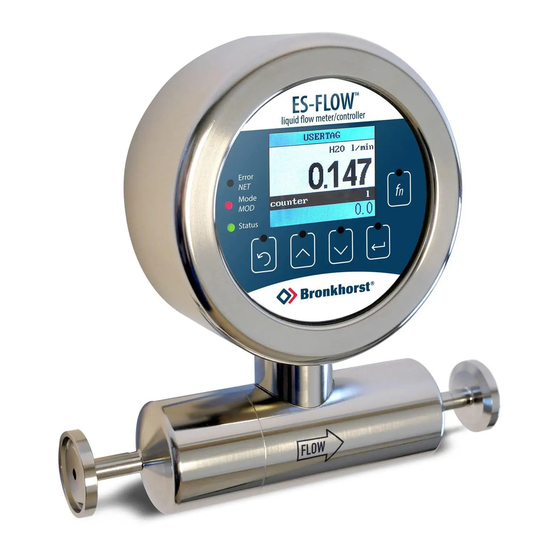
ES-FLOW™
Ultrasonic Volume Flow Meter/Controller
Doc. no.: 9.17.116B
Date: 19-12-2017
ATTENTION
Please read this Instruction Manual carefully before installing and operating the instrument.
Not following the guidelines could result in personal injury and/or damage to the equipment.
Advertisement
Table of Contents

Related Manuals for BRONKHORST ES-FLOW


Summary of Contents for BRONKHORST ES-FLOW
- Page 1 Instruction Manual ES-FLOW™ Ultrasonic Volume Flow Meter/Controller Doc. no.: 9.17.116B Date: 19-12-2017 ATTENTION Please read this Instruction Manual carefully before installing and operating the instrument. Not following the guidelines could result in personal injury and/or damage to the equipment.
- Page 2 Subject to technical and optical changes as well as printing errors. The information contained in this document is subject to change at any time without prior notification. Bronkhorst High-Tech B.V. reserves the right to modify or improve its products and modify the contents without being obliged to inform any particular persons or organizations. The device specifications and the contents of the package may deviate from what is stated in this document.
- Page 3 Bronkhorst® Warranty Bronkhorst® products are warranted against defects in material and workmanship for a period of three years from the date of shipment, provided they are used in accordance with the ordering specifications and not subject to abuse or physical damage.
- Page 4 Bronkhorst® Instruction Manual ES-FLOW™ 9.17.116B...
-
Page 5: Table Of Contents
......................33 9.17.116B Instruction Manual ES-FLOW™... - Page 6 ......................48 Instruction Manual ES-FLOW™...
-
Page 7: Introduction
Bronkhorst High-Tech B.V. cannot be held liable for any damage resulting from improper use or use for other than the intended purpose. Product description The ES-FLOW™ is a precise and compact volume flow meter with control function for liquids, based on a novel ultrasonic technology. Measuring principle Measuring is done in a straight tube, without obstructions or dead spaces. -
Page 8: Other Documents
The ES-FLOW™ comes with all necessary information for basic operation and maintenance. This section lists all documentation that is relevant to the ES-FLOW™. Some documents are not necessarily part of the scope of delivery, but can be provided on request. Documents with a check mark in the column labeled 'www' can be downloaded from http://www.bronkhorst.com/en/downloads. -
Page 9: Model Key
Bronkhorst® Model key 9.17.116B Instruction Manual ES-FLOW™... -
Page 10: Customized I/O Options
Customized I/O options ES-FLOW™ instruments offer various customized input/output functions through pin 5 of the M12 connector and through pin 2 of the M8 connector as an option. I/O options are factory installed as specified at ordering time, and cannot be changed manually. - Page 11 (controller enabled, see model key). · If the controller is enabled, the M8 connector can always be used to control a Bronkhorst® valve (through pin 3). · Although it is theoretically possible to have 3 controller options installed, no more than 1 signal should be used at any time.
-
Page 12: Installation
· Ambient temperature · Input and output signal Bronkhorst® instruments are pressure tested to 1.5 times the requested pressure rating and outboard leak tested to at least 2 * 10 mbar l/s Helium. The tested pressure is specified on the product label. If the product label is missing or if the specified pressure is insufficient, the instrument must not be used and should be returned to the factory. -
Page 13: Fluidic Connections
Fluidic connections The FLOW arrow on the measuring tube indicates the normal flow direction. For normal use, install the ES-FLOW™ in the process line, in accordance with the direction of the FLOW arrow. For bi-directional measuring, install the instrument in the direction where the highest flow will be measured (if applicable). -
Page 14: Communication Interface
Bronkhorst® Communication interface Check if the default network settings match the configuration of the fieldbus system (if applicable). If necessary, the default settings can be overruled by changing the appropriate parameters (see Network configuration). Instruction Manual ES-FLOW™ 9.17.116B... -
Page 15: Operation
For controllers, give setpoint = 100% or use special Control mode = 8 (valve fully open), to ensure getting the highest possible flow rate. Control mode 8 bypasses the PID controller, which is particularly useful when having the ES-FLOW™ set to a low capacity flow range. User interface The screen representations in this section are for illustration purposes only. -
Page 16: Main Screen Functions
· To cycle through the editable screen areas, press repeatedly · To enter edit mode for the selected area, press · When edit mode is active, press at any time to leave edit mode without making changes Instruction Manual ES-FLOW™ 9.17.116B... -
Page 17: Editing Setpoint
3.3.1.5 Resetting counter 1. In the main screen, 2. Press to enter edit 3. Press 4. Press to confirm the select the Custom mode: change the value to selected option and readout 2 area: 'yes': reset the counter: 9.17.116B Instruction Manual ES-FLOW™... -
Page 18: Resetting Alarm
· Second line: current parameter value Not all parameters can be edited; some parameter values are protected, or display a value that is directly linked to the value of another parameter: Normal display Parameter can be edited Parameter is read-only Dimmed Instruction Manual ES-FLOW™ 9.17.116B... -
Page 19: Password Protection
(the first the required the next character character position is character/digit: position: highlighted): On confirmation of the last character/digit, the entered value is stored and edit mode is left (wherupon the character highlight is removed). 9.17.116B Instruction Manual ES-FLOW™... -
Page 20: Editing List Selection
Description Supported values Readout format Display format of the measured value in the main screen · actual · percentage Fluid Selected (metered) fluid As ordered Capacity Maximum readout/control value (100%) for the selected fluid As ordered Instruction Manual ES-FLOW™ 9.17.116B... -
Page 21: Controller
The Controller sub menu is only available if the control function of the instrument is enabled. This setting is part of the instrument configuration at the factory. Because controlling characteristics are optimized during manufacture, Bronkhorst strongly advises not to change these parameters. If changing controller settings is absolutely necessary, it should be performed by or under supervision of trained service personnel only. -
Page 22: Counter
3.3.3.3 Counter Bronkhorst® flow meters have a built-in counter function, which can be used to monitor and/or control the amount of media flowing through the instrument. The flow can be stopped or changed when a certain limit is reached. Until the counter is reset, the counter setpoint overrules the regular setpoint. -
Page 23: Setup
(after the alarm situation was activated) Setpoint change Specifies whether or not to change the setpoint after an · yes alarm situation is activated · no Setpoint New setpoint until alarm reset Setpoint range 3.3.3.5 Setup 9.17.116B Instruction Manual ES-FLOW™... -
Page 24: Advanced
In the Advanced sub menu, the following parameters can be edited: Parameter/function Description Supported values Dynamic filter 0…1 Static filter 0…1 Autozero Function for adjusting zero point (only for flow meters/controllers) Restore Function for restoring instrument settings Instruction Manual ES-FLOW™ 9.17.116B... -
Page 25: Security Menu
· Enabled: item is available without restrictions · Disabled: item is not available · Password: item is password protected The password protection of the Security menu itself cannot be removed, nor can the menu be disabled. 9.17.116B Instruction Manual ES-FLOW™... -
Page 26: Changing Password
If the password is lost (after changing it), it can be reset by entering an encrypted key. This reset key can be obtained by sending a so-called 'bht key' to your local Bronkhorst representative. After entering the reset key, the password will be reset to the default value ('abc'). -
Page 27: Led Indications
Wink mode; by sending a command to the Wink parameter, the instrument flashes its 0.2 sec off LEDs to indicate its position in a (large) system. fast wink 0.1 sec on, Selected action started (after releasing the multifunctional switch) 0.1 sec off 9.17.116B Instruction Manual ES-FLOW™... -
Page 28: Devicenet
The available functions are presented in a repeating sequence of patterns, where each pattern indicates a special function. To select and start a function, press and hold the switch until the LEDs show the pattern of the function to be started. By releasing the switch, the selected function is started. Instruction Manual ES-FLOW™ 9.17.116B... - Page 29 3. Subtract 8 from the read value 4. Write the new value to parameter IO status 5. Set parameter Init reset to 82 To re-enable te switch, add 8 to the value of IO status in step 3. 9.17.116B Instruction Manual ES-FLOW™...
-
Page 30: Digital Parameters
FLOW-BUS In a FLOW-BUS system, instrument configuration and operation can be done using the free Bronkhorst® FlowWare tools. These tools provide a graphical interface to the ProPar protocol (used by FLOW-BUS), for monitoring and changing instrument settings. Digital communication between the instrument and the client software (e.g. FlowPlot, FlowTune™) is handled by FlowDDE, a Dynamic Data Exchange server (DDE), the core component of the FlowWare software. -
Page 31: Special Parameters
[Par] Parameter number Consult Instruction manual RS232 interface (document no. 9.17.027) for detailed information. This document can be downloaded from http://www.bronkhorst.com/en/downloads Modbus In the Modbus protocol, parameters are accessed by specifying their unique decimal register number or corresponding PDU address (Protocol Data Unit). The PDU address is the hexadecimal translation of the register number minus 1, e.g. register... - Page 32 If Control mode is set to value 0, 1, 9 or 18, the instrument returns to its default control mode at the next power-up or reset. Other values are retained after power-up or reset. Instruction Manual ES-FLOW™ 9.17.116B...
-
Page 33: Default Control Mode
33/0 0xA100…0xA101/ 41217…41218 3.4E+38 Floating point variant of Measure. Fmeasure shows the measured value in the capacity and capacity unit for which the instrument has been set. Fmeasure is dependent of Capacity Unit and Sensor Type. 9.17.116B Instruction Manual ES-FLOW™... -
Page 34: Device Identification
This parameter is used to add extra information to the model number information, such as a customer-specific model number. Serial Number Type Access Range FlowDDE FLOW-BUS Modbus Unsigned char[20] R 113/3 0xF118…0xF11F/ 61721…61728 Instrument serial number for identification. Instruction Manual ES-FLOW™ 9.17.116B... -
Page 35: Alarms
Device type information string; this parameter contains an abbreviation referring to the identification number. 3.4.5 Alarms Alarm settings are most easily accessible via FlowPlot or FlowView or a Bronkhorst® readout and control unit. The built-in alarm functionality can be used to handle different alarm types: · system errors and warnings ·... - Page 36 Access Range FlowDDE FLOW-BUS Modbus Unsigned char 0…1 97/5 0x0C25/3110 Specifies whether or not to change the setpoint after an alarm situation is activated. Value Description No setpoint change (default) Change setpoint to Alarm new setpoint Instruction Manual ES-FLOW™ 9.17.116B...
-
Page 37: Counter
Description Multifunctional switch External By parameter Reset Automatically (when alarm conditions no longer apply) 3.4.6 Counter Counter settings are most easily accessible via FlowPlot or FlowView or a Bronkhorst® readout and control unit. Counter Mode Type Access Range FlowDDE FLOW-BUS... -
Page 38: Network Configuration
Network configuration Changes made to the network settings will not be restored by a factory reset. Communication via fieldbus connection (RS485) Use the following parameters to configure the instrument for communication via the fieldbus connection (5-pin M12): Instruction Manual ES-FLOW™ 9.17.116B... - Page 39 Unsigned long RW 0…1.0E10 124/9 0xFC48…0xFC49/64585…64586 Bus 2 Parity Type Access Range FlowDDE FLOW-BUS Modbus Unsigned char RW 0…2 124/12 0x0F8C/3981 The following values are supported: Value Description No parity Odd parity Even parity 9.17.116B Instruction Manual ES-FLOW™...
-
Page 40: Controller
· Open from zero: the setpoint is larger than zero and the measured value is below 2% of the full scale range. · Normal step: the measured value differs more than 2% from the setpoint, typically after changing the setpoint (step). · Stable situation: the measured value differs less than 2% from the setpoint. Instruction Manual ES-FLOW™ 9.17.116B... - Page 41 Bronkhorst® Because controlling characteristics are optimized during manufacture, Bronkhorst strongly advises not to change these parameters. If changing controller settings is absolutely necessary, it should be performed by or under supervision of trained service personnel only. Controller Speed Type Access...
-
Page 42: Master/Slave Configuration
· the instrument is filled homogeneously with the operational media · there is absolutely no fluid flow through the instrument; preferably, this is done by closing valves directly after the outlet of the instrument (control valve, shut-off valve) Instruction Manual ES-FLOW™ 9.17.116B... -
Page 43: Autozero Function
If the procedure was successful, parameter Calibration mode changes to 0 (idle). If the procedure fails, Calibration mode changes to 255. After performing the procedure, remember to set parameter Init reset to value 0 to lock secured parameters 9.17.116B Instruction Manual ES-FLOW™... -
Page 44: Maintenance
Maintenance General No regular maintenance is required if the ES-FLOW is operated properly, with clean media, compatible with the wetted materials, avoiding pressure and thermal shocks and vibrations. Units may be purged with a clean, dry and inert gas. In case of severe contamination, cleaning the inside of the device may be required. After cleaning, the instrument has to be re-calibrated. -
Page 45: Troubleshooting And Service
Invalid node address Change node address (see Network configuration) Other Reset instrument and/or restart master. If problem persists, contact Bronkhorst. No output signal No power supply · Check power supply · Check cable connection · Check cable hook-up Sensor failure... - Page 46 Check the system for leakage. Follow vendor instructions when installing third party components (e.g. adapters, tubing, valves) Continuous maximum measured Inlet pressure too high Check inlet pressure value or output signal Sensor failure Return equipment to factory Instruction Manual ES-FLOW™ 9.17.116B...
-
Page 47: Service
Bronkhorst® Service For current information on Bronkhorst® and service addresses, please visit our website: http://www.bronkhorst.com Do you have any questions about our products? Our Sales Department will gladly assist you selecting the right product for your application. Contact sales by e-mail: ›... -
Page 48: Removal And Return Instructions
A 'Declaration on decontamination' form (document no 9.17.032) can be downloaded from http://www.bronkhorst.com/en/downloads. Important: Clearly note, on top of the package, the customs clearance number of Bronkhorst High-Tech B.V., namely: NL801989978B01 (only if applicable, otherwise contact your distributor for local arrangements.) Instruction Manual ES-FLOW™...
Need help?
Do you have a question about the ES-FLOW and is the answer not in the manual?
Questions and answers