Table of Contents
Advertisement
Quick Links
Advertisement
Table of Contents

Related Manuals for BRONKHORST ES-FLOW ES Series


Summary of Contents for BRONKHORST ES-FLOW ES Series
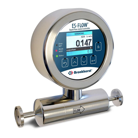
- Page 1 Instruction Manual ES-FLOW™ Ultrasonic Volume Flow Meter/Controller Doc. no.: 9.17.145 rev. E Date: 02-11-2020 ATTENTION Please read this document carefully before installing and operating the product. Not following the guidelines could result in personal injury and/or damage to the equipment.
- Page 2 Disclaimer This document has been reviewed and is believed to be accurate. Bronkhorst High-Tech B.V. does not assume liability for errors, inaccuracies or absence of information. The material in this document merely serves information and illustration purposes;...
- Page 3 Bronkhorst® Warranty Bronkhorst® products are warranted against defects in material and workmanship for a period of three years from the date of shipment, provided they are used in accordance with the ordering specifications and not subject to abuse or physical damage.
- Page 4 Bronkhorst® Instruction Manual ES-FLOW™ 9.17.145E...
-
Page 5: Table Of Contents
Bronkhorst® Table of contents Introduction ......................7 Scope of this manual . - Page 6 Bronkhorst® 3.3.6.2 Control mode - readout/change ......................31 3.3.6.3...
-
Page 7: Introduction
Material Safety Data Sheets of the media to be used in the system (if applicable). Bronkhorst High-Tech B.V. cannot be held liable for any damage resulting from improper or unsafe use, use for other than the intended purpose or use with other media and/or under other conditions than specified on the purchase order. -
Page 8: Documentation
Bronkhorst® Application The combination of a straight sensor tube with zero dead volume, self-drainability and hygienic connections, makes the ES- FLOW especially suitable for hygienic applications. Examples of typical use are the measuring of food ingredients like flavourings or syrups, or measuring concentrates in CIP units. For non-hygienic applications, the instrument can be equipped with compression type fittings. -
Page 9: Model Key
Bronkhorst® The documentation listed in the following table can be downloaded from www.bronkhorst.com/downloads Type Document Document no. Manuals Manual CANopen interface 9.17.131 Manual DeviceNet™ interface 9.17.026 Manual EtherCAT interface 9.17.063 Manual EtherNet/IP interface 9.17.132 Manual FLOW-BUS interface 9.17.024 Manual Modbus ASCII/RTU/TCP interface 9.17.035... -
Page 10: Customized I/O Options
Bronkhorst® 1.5.1 Customized I/O options ES-FLOW™ instruments offer various customized input/output functions through pin 5 of the M12 connector and through pin 2 of the M8 connector as an option. I/O options are factory installed as specified at ordering time, and cannot be changed manually. - Page 11 (controller enabled, see model key). · If the controller is enabled, the M8 connector can always be used to control a Bronkhorst® valve (through pin 3). · Although it is theoretically possible to have 3 controller options installed, no more than 1 signal should be used at any time.
-
Page 12: Installation
· Ambient temperature · Input and output signal Bronkhorst® instruments are pressure tested to 1.5 times the requested pressure rating and outboard leak tested to at least 2 * 10 mbar l/s Helium. The tested pressure is specified on the serial number label. If the serial number label is missing or if the specified pressure is insufficient, the instrument must not be used and should be returned to the factory. -
Page 13: Orientation
Its orientation can only be altered by repositioning the entire instrument. On models starting from MkII, the flow direction and display orientation can be adjusted at the factory, for which the instrument has to be returned. Contact your Bronkhorst representative for more information and arrangements. 2.2.3 Hygienic applications In order to comply with the 3-A Sanitary Standards, the ES-FLOW™... -
Page 14: Electrical Connections
The device carries the CE-mark and is compliant with the concerning EMC requirements. However, EMC requirements can only be met using appropriate cables and connector/gland assemblies. Bronkhorst recommends the use of their standard cables. These cables have the right connectors and loose ends (if any) are marked to help prevent wrong connection. -
Page 15: Operation
First use Bronkhorst does the utmost to ensure that you receive a clean product.This does not, however, relieve the end user of the responsibility to ensure that the instrument and the system in which it is incorporated meet (hygiene) requirements that apply to the intended use of the instrument. -
Page 16: Main Screen Functions
Bronkhorst® The communication status of the instrument can be monitored with the three LEDs to the left of the screen. See LED indications for a description of the possible indications. A multifunctional switch ( ) to the right of the screen can be... -
Page 17: Editing Setpoint
Bronkhorst® 3.3.1.4 Editing setpoint · The setpoint of a controlling instrument can be changed if the parameter is displayed in the custom readout area. · Instruments without a control function have no editable setpoint and can only be monitored (Custom readout 1 not available). -
Page 18: Resetting Alarm
Bronkhorst® 3.3.1.6 Resetting alarm Before resetting the alarm, be sure to eliminate the cause. Resetting the alarm without changing the conditions that caused it will re-activate the alarm immediately. When an alarm occurs, a message blinks in the top line of the main screen. If the alarm is configured to be reset automatically, the blinking stops as soon as the alarm conditions no longer apply. -
Page 19: Password Protection
Bronkhorst® Navigation · Inside menus and sub menus, the selected item is highlighted in red · Press to navigate to the required menu item · Arrows pointing up and/or down in the top line indicate the menu contains more items than can be displayed. -
Page 20: Editing List Selection
Bronkhorst® 3.3.2.3 Editing list selection 1. Select the parameter to 2. Press to enter edit 3. Press to scroll 4. Press to confirm the be edited: mode (the selected through the available selected option and value is highlighted): options: leave edit mode (the highlight is removed): 3.3.3... -
Page 21: Controller
Bronkhorst® In the Readout sub menu, the following parameters can be edited: Parameter Description Supported values Readout format Display format of measured value in main screen · actual · percentage Type* Measurement type · volume Note: value 'mass' can only be selected if parameter Density >... -
Page 22: Counter/Totalizer
Counter/totalizer Bronkhorst® flow meters have a built-in counter function, which can be used to monitor and/or control the amount of media flowing through the instrument. The flow can be stopped or changed when a certain limit is reached. Until the counter is reset, the counter setpoint overrides the regular setpoint. - Page 23 Bronkhorst® The Counter sub menu provides the following parameters and functions: Parameter Description Supported values Counter mode Selected counter mode · off · up to limit · up Counter reset Reset method · automatic · manual Type* Measurement type · volume Note: changing this setting will reset both the counter and ·...
-
Page 24: Alarm
Bronkhorst® 3.3.3.4 Alarm In the Alarm sub menu, the following parameters can be edited: Parameter Description Supported values Mode Alarm type · off · min/max · response · power-up Reset Reset method; reset alarm automatically if alarm conditions · automatic no longer apply, or manually via the user interface ·... -
Page 25: Setup
Bronkhorst® 3.3.3.5 Setup 9.17.145E Instruction Manual ES-FLOW™... -
Page 26: Advanced
Bronkhorst® The following parameters are available in the Setup sub menu: Parameter Description Supported values Usertag Custom instrument name text (16 positions) Serial Instrument serial number n/a (read only) Model Instrument model number n/a (read only) Firmware version Firmware version... -
Page 27: Security Menu
Bronkhorst® 3.3.4 Security menu In the Security menu, access to some delicate items can be restricted. The password that is used for password protected items can also be changed here. The following items can be restricted: Item Description Edit setpoint... -
Page 28: Changing Password
If the password is lost (after changing it), it can be reset by entering an encrypted key. This reset key can be obtained by sending a so-called 'bht key' to your Bronkhorst representative. After entering the reset key, the password will be reset to the default value ('abc'). -
Page 29: Led Indications
Bronkhorst® 3.3.5 LED indications • (green) Mode/MOD: operation mode indication • (red) Error/NET: error/warning messages The tables below list the different LED indications: • Green Pattern Time Indication continuous Power-off or program not running continuous Normal operation mode short flash 0.1 sec on,... -
Page 30: Interface Status
Bronkhorst® 3.3.5.1 Interface status Instruments with a PROFINET interface are equipped with a third LED (bi-color; green and red), to indicate the status of the communication interface. This Status LED can give the following indications: Pattern Time Indication • continuous Power off •... -
Page 31: Normal Operating Functions
Bronkhorst® 3.3.6.1 Normal operating functions · In order to access these functions, press and hold the switch while the instrument is in normal operation mode (green LED glowing). · As long as the switch is held, the LEDs show a repeating sequence of patterns, where each pattern indicates a function. -
Page 32: Network Settings - Readout/Change
Bronkhorst® To execute a step, follow these instructions: · Press and hold the switch (flashing slows) · To select value 0 (zero), release the switch within 1 second, otherwise: · Count the number of LED flashes · Release the switch when the required value is reached ·... -
Page 33: Disabling Multifunctional Switch
Bronkhorst® Changing network settings · By briefly pressing the switch 5 times with intervals of up to 1 second in normal operation mode, the instrument enters a state in which the node address and baud rate can be changed (non-Ethernet based protocols only; for Ethernet based protocols like PROFINET, network parameters are configured by the fieldbus master and cannot be set on the instrument). -
Page 34: Digital Parameters
Each communication protocol uses its own methods for communicating with instruments and accessing parameters. FLOW-BUS Digital Bronkhorst® instruments can be monitored and operated via RS-232 using the free FlowWare software tools for Windows. These tools provide a graphical interface to the ProPar protocol (used by FLOW-BUS), for monitoring and changing instrument parameters. -
Page 35: General
DeviceNet™ system, including communication and network configuration, and all available operating parameters with their data types. An EDS file for Bronkhorst® instruments can be downloaded from the product pages on the Bronkhorst website: www.bronkhorst.com/products 3.4.1... -
Page 36: Measurement And Control
Bronkhorst® 3.4.2 Measurement and control Measure Type Access Range FlowDDE FLOW-BUS Modbus Unsigned int 0…41942 0x0020/33 (65535*) This parameter indicates the flow metered by the instrument. The value of 32000 corresponds to 100%, the maximum measured value output is 131.07%, which translates to 41942. -
Page 37: Alarms
This parameter represents the controller output signal for control valve operation. 3.4.3 Alarms Alarm settings are most easily accessible using FlowPlot or FlowView or a Bronkhorst® readout and control unit. The built-in alarm functionality can be used to handle different alarm types: · system errors and warnings ·... - Page 38 Bronkhorst® Alarm Info Type Access Range FlowDDE FLOW-BUS Modbus Unsigned char 0…255 1/20 0x0034/53 This parameter provides information about the event type(s) that triggered an alarm situation. The value is a bitwise summation of the issued alarm types; convert the value to binary to see which types are issued. The following alarm types...
-
Page 39: Counter And Totalizer
Multifunctional switch Externally (deprecated) By parameter Reset Automatically (when alarm conditions no longer apply) 3.4.4 Counter and totalizer Counter settings are most easily accessible using FlowPlot or FlowView or a Bronkhorst® readout and control unit. Counter Mode Type Access Range FlowDDE... - Page 40 Bronkhorst® Counter Value Type Access Range FlowDDE FLOW-BUS Modbus Float 0… 104/1 0xE808…0xE809/59401…59402 10000000 Current counter value in units selected with parameter Counter Unit. Counter Limit Type Access Range FlowDDE FLOW-BUS Modbus Float 0…9999999 104/3 0xE818…0xE819/59417…59418 Counter limit/batch size in units selected with parameter Counter Unit.
-
Page 41: Network Configuration
Bronkhorst® Totalizer Value Type Access Range FlowDDE FLOW-BUS Modbus Float 0… 104/17 0xE888…0xE889/59529…59530 10000000 Current totalizer value in units as selected with parameter Totalizer Unit. 3.4.5 Network configuration Changes made to the network settings will not be restored by a factory reset. -
Page 42: Controller
Controller The picture below shows a basic diagram of the PID controller algorithm (proportional, integral, derivative) used by digital Bronkhorst® instruments. The controller speed controls the overall performance of the controller algorithm. Basically, to adjust the controller response, only the controller speed needs to be changed. - Page 43 Bronkhorst® The control characteristics are optimized during production. These parameters should only be changed if absolutely necessary, and only by or under the supervision of trained service personnel. Controller Speed Type Access Range FlowDDE FLOW-BUS Modbus Float 0.2…5 114/30 0xF2F0…0xF2F1/62193…62194 This parameter sets the overall controller speed factor for the selected fluid set.
-
Page 44: Master/Slave Configuration (Flow-Bus)
Bronkhorst® 3.4.7 Master/slave configuration (FLOW-BUS) Normally, there is no communication between slave instruments in a fieldbus system. The FLOW-BUS protocol, however, provides a feature to set up a master/slave relationship between two instruments. The typical behavior of a slave instrument is to automatically set its own setpoint relative to the output (measurement value) of its master. -
Page 45: Special Parameters
BHT Model Number Type Access Range FlowDDE FLOW-BUS Modbus Unsigned char[35] RW 113/2 0xF110…0xF117/ 61713…61720 This parameter shows the Bronkhorst® instrument model type information. Firmware Version Type Access Range FlowDDE FLOW-BUS Modbus Unsigned char[6] 113/5 0xF128…0xF12A/ 61737…61739 Revision number of the firmware... - Page 46 Bronkhorst® Value Description No reset Reset counter Reset alarm Reset counter Reset and disable counter Reset firmware program (soft reset) Reset Alarm info error bit Reset Alarm info warning bit Reset totalizer The Reset parameter may be disabled by Reset Alarm Enable or Reset Counter Enable. Make sure the value is accepted by sending value 0 first.
-
Page 47: Default Control Mode
Adjusting zero point The zero point (the signal that corresponds to zero flow) of a Bronkhorst® flow meter/controller is factory adjusted at approximately 20 °C and atmospheric pressure, with the instrument in an upright position. If the ambient conditions or mounting position are significantly different, the instrument might detect a flow when actually there is none. -
Page 48: Autozero Function
Bronkhorst® 3.5.1 Autozero function The readout and control unit provides an automatic function for re-adjusting the zero-point of a flow meter, which automatically steps through the required parameter settings. This autozero function can be found in the Advanced section of the Settings menu: 1. -
Page 49: Maintenance
Inexpertly servicing instruments can lead to serious personal injury and/or damage to the instrument or the system it is used in. Servicing must therefore be performed by trained and qualified personnel. Contact your Bronkhorst representative for information about cleaning and calibration. Bronkhorst has a trained staff available. -
Page 50: Troubleshooting And Service
Energizing and de-energizing the equipment can indicate whether there is an electronic failure. After energizing, control behavior can be checked by applying fluid pressure. If you suspect leakage, do not disassemble the device for inspection, but contact your Bronkhorst representative for service or repairs. - Page 51 Check the system for leakage. Follow vendor instructions when installing third party components (e.g. adapters, tubing, valves) Continuous maximum measured Inlet pressure too high Check inlet pressure value or output signal Sensor failure Contact your Bronkhorst representative 9.17.145E Instruction Manual ES-FLOW™...
-
Page 52: Service
Bronkhorst representative about a specific item. The serial number (SN) is the key to the original purchase order and can be found on the product. -
Page 53: Returns
All Bronkhorst® products covered by the WEEE directive (the majority) carry an image of a crossed-out waste bin (usually on the serial number label). If you wish to dispose of Bronkhorst® equipment bearing this... - Page 54 Bronkhorst® Instruction Manual ES-FLOW™ 9.17.145E...
-
Page 55: Parameter Index
Bronkhorst® Temperature Parameter index Valve Output Parameters Parameters - Network configuration Fieldbus1 Address Parameters - Alarms Fieldbus1 Baud Rate Alarm Delay Time Fieldbus1 Parity Alarm Info Fieldbus2 Address Alarm Maximum Limit Fieldbus2 Baud Rate Alarm Minimum Limit Fieldbus2 Parity Alarm Mode...
Need help?
Do you have a question about the ES-FLOW ES Series and is the answer not in the manual?
Questions and answers