Advertisement
Quick Links
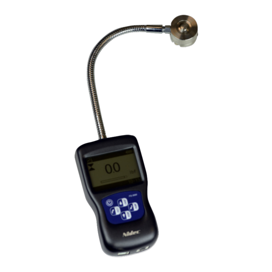
FG-3000R Digital Force Gauge
Operation Manual
Operators should wear protection such as a mask and gloves in case
pieces or components break away from the unit under test.
Whether the unit is ON or OFF, DO NOT exceed the capacity of the
gauge. NEVER exceed 150% of the rated capacity, or the load cell will
be damaged. At 110% of the rated capacity, the display will flash a
warning.
When mounting FG-3000 Series Digital Force Gauges, use M4 mount-
ing screws with a maximum insertion depth of 7 mm into the gauge.
Hand tighten mounting screws, DO NOT use tools. Do not use damaged
clamp.
Measure in line tension and compression forces only. DO NOT attempt
to measure forces at an angle to the measuring shaft – damage to load
cell and/or shaft may result.
Do not attempt to repair or alter this instrument. Warranty will be voided
and damage to the unit may result.
Use and store within the stated temperature and humidity ranges, or
damage and failure may result.
When using adapter measuring heads, do not use tools. Hand tighten
only.
The new FG-3000R Series digital force gauges are the choice for
simple, cost-effective compression testing. Combining one of the
most compact housings, yet maintaining a large back-lit LCD,
these units were designed to fit perfectly in the hand for ease of
use. The multi-language FG-3000's provide menu programming
for intuitive set-up of the instrument to your desired requirements.
Three modes of operation are selectable: Track mode displays
live readings, Peak mode records the maximum reading sensed
during the test, and Pre-set mode which activates user defined
high and low limit set points. The programmable limits provide a
quick visual and audible indication if a test passes or fails. In ad-
dition, a comparator output enables integration of the instrument
into your quality system for repetitive testing such as on produc-
tion lines.
The integral button style load-cell attached via the flexible, metal
braided cable enables reading to be taken in machinery or fix-
tures where other force gauge adapters are unable to reach or fit.
The display graphics facilitate user comprehension and opera-
tion. An analog bar graph provides perspective of current reading
in comparison to the full scale range. Pass/Fail icons provide an
instant response of the testing outcome while a storage symbol
acknowledges when a reading is logged. A menu-selectable dis-
play orientation streamlines switching from push to pull testing for
portable or test stand applications.
4
3
5
6
7
10
SEALS USA, Inc.
Instruments Division
SPECIFICATIONS
Accuracy: ± 0.5% F.S.
Selectable Units: kN, kgf, N, klbf and lbf. (Depending on Range)
Overload Capacity: 150% of F.S. (LCD flashes beyond 110% of
F.S.)
Measurement Method: Peak, Track, Preset
Data Sampling Rate: 1000 Hz
Display: 160*128 dot matrix LCD with Backlight
Display Update Rate: 10 times/second
Resolution: (See chart)
Memory: 500 data
Set Point: Programmable high and low limits in Preset Mode
Battery Indicator: Display flashes battery icon when battery is
low
Power: 3.6VDC 800mAH Ni-MH rechargeable batteries
Battery Life: Approximately 16 hours continuous use per full
charge
Charger / Adaptor: Universal USB/BM charger, Input: 110 ~
240VAC
Temperature Effects: <0.054% per °F (0.03% FS per °C)
Outputs: USB, RS-232; High & Low Limit NPN's
Operating Temperature: 14 to 104°F (-10 to 40°C)
Storage Relative Humidity: 20 to 80%
Housing: Aluminum
Storage Temperature: -4 to 122°F (-20 to 50°C)
Oper. Relative Humidity: 5 to 95%
Dimensions: 5.5 x 2.8 x 1.4" (140 x 71 x 35.5 mm)
Product Weight: 1.1 lb (0.5 kg)
Package Weight: 2.8 lb (1.3 kg)
Warranty: 1 year
Certification: CE
Included Accessories: AC Adaptor/Charger, USB cable, calibra-
tion cert., carrying case
LCD Screen
1
1. Battery icon: Battery level or charging status. Flashes when
2. OK/OV Indicator:
2
3. Force icon: Indicates force direction.
9
4. Test mode icon: Three measurement modes: Track, Peak
5. Current meaured value
6. Analog bar: Indicates current position within full scale. When
8
7. Storage icon: Indicates data is being saved.
8. System time
9. Units Indicator: Selected engineering unit.
10. Data Transmission icon
gauge needs to be recharged.
Measured value between low limit
and upper limit;
Value over upper limit
Value between lower limit and 75% of lower limit
Compression
and Preset
the bar enters the area enclosed by the dotted line, it means
full scale capacity is exceeded and overload.
Tel: (630)924-7138
Tension
Email: support@seals-usa.com
Advertisement

Related Manuals for Nidec FG-3000R Series


Summary of Contents for Nidec FG-3000R Series
- Page 1 Overload Capacity: 150% of F.S. (LCD flashes beyond 110% of F.S.) Measurement Method: Peak, Track, Preset The new FG-3000R Series digital force gauges are the choice for Data Sampling Rate: 1000 Hz simple, cost-effective compression testing. Combining one of the...
- Page 2 “ZERO” or “MODE” keys to shift to the next selection. Press “LOG” visual indicators. to cancel or touch “MENU” to confirm and exit. (Fig. 3-2) 1.3 Menu Structure The FG-3000R Series Force Gauge has multi-level menu interface (Table 1-3) that enables simple navigation and programming. MENUS SUBMENUS...
-
Page 3: Saving The Measured Value
You can also select the mode under the Measurement menu in 4.1 Memory the Test Mode sub-menu. See Fig. 3-3(a) If the Preset is selected, a new screen will pop up where you can set the Upper and Lower limits. See Fig 3-3(b) Press ZERO to adjust the number and press MODE to move to the next digit. - Page 4 Fig. 4-3(a) Fig. 5-1(a) Reverse Obverse Fig. 4-3(b) Fig. 5-1(b) 4.4 Delete All 5.2 Auto Power All data points can be cleared from memory under the Delete all The FG-3000R has an automatic power off function. With Auto sub-menu (Fig. 4-4). A confirm window will appear asking you to Power on, if there is no operation performed within five minutes it confirm.
-
Page 5: Communication Port
5.6 Calibration Because of the sensor material performance or the influence of external factors, there may be errors of a certain level after a period of usage. It is recommended to send the force gauge to a specialized test- ing organization for calibration. Fig. -
Page 6: Troubleshooting
Do not disassemble the gauge by your- RS-232 Specifications: self or attempt to repair. If you cannot resolve the fault yourself, -Hardware Flow Control: None please contact Nidec-Shimpo. -Data word length: 8 bits -Stop bit: 1bit -Parity: None... - Page 7 11. CAPACITY AND RESOLUTION Model klbf Capacity 1000 FG-3000R-1 Resolution 0.001 0.01 0.01 Capacity 5000 1100 FG-3000R-5 Resolution 0.001 Capacity 1000 2250 FG-3000R-10 Resolution 0.01 Capacity 2000 4500 FG-3000R-20 Resolution 0.01 Capacity 50.0 5000 FG-3000R-50 Resolution 0.01 0.01...
- Page 8 SEALS USA, Inc. Instruments Division Tel: (630)924-7138 Email: support@seals-usa.com...