Advertisement
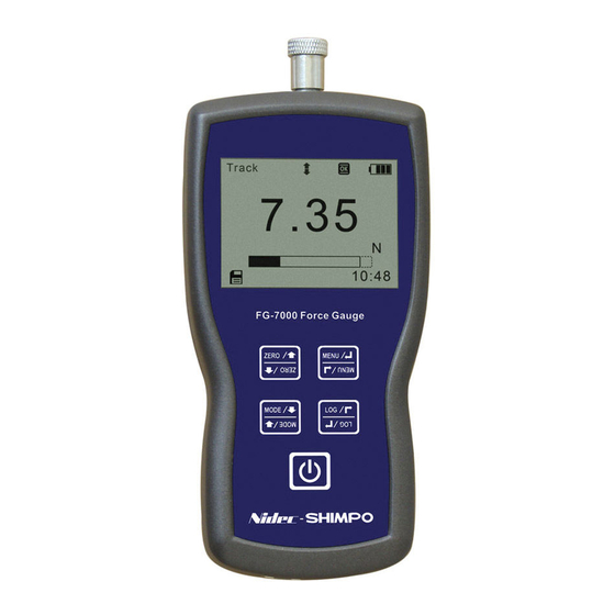
FG-7000L Digital Force Gauge
Operation Manual
Operators should wear protection such as a mask and gloves in case
pieces or components break away from the unit under test.
Whether the unit is ON or OFF, DO NOT exceed the capacity of the
sensor. NEVER exceed 150% of the rated capacity for S beam, or 120%
for ring type, or the load cell will be damaged. At 110% of the rated
capacity the display will flash a warning.
When mounting FG-7000L Series Digital Force Gauges, use M4 mount-
ing screws with a maximum insertion depth of 7 mm into the gauge.
Hand tightens mounting screws, DO NOT use tools. Do not use dam-
aged clamp.
Measure in line tension and compression forces only. DO NOT attempt
to measure forces at an angle to the sensor – damage to load cell may
result.
Do not attempt to repair or alter this instrument. Warranty will be voided
and damage to the unit may result.
Use and store within the stated temperature and humidity ranges, or
damage and failure may result.
If not using this instrument for extended periods of time, remove the
batteries to prevent potential battery leakage from causing product
damage.
DO NOT use tools to over torque the connection adapter. Hand-tighten
only so damage does not occur.
The FG-7000L Series digital force gauges provide additional ten-
sion and compression testing flexibility with their external load cell
input. External load cells are immediately recognized when con-
nected to the display base. Three styles of load cells are available
for your specific testing needs. The first is the 'S' Beam style load
cell for both tension and compression tests with capacities rang-
ing from 220 lbf (100 kgf) up to 4500 lbf (2000 kgf). The second
style available is the 'Ring' type load cell for compression applica-
tions with capacities ranging from 2250 lbf (1000 kgf) all the way
up to a hefty 44,000 lbf (200 kN). The third style is the "Mini Ring"
type load cell for compression applications with capacities from
220 lbg (100 kgf) to22 klbf (10,000 kgf).
The multiple-language FG-7000L's provide menu programming
for easy selection and set-up of the instrument to your desired
requirements. Four selectable modes of operation include: Track
mode for live readings, Peak mode for displaying the maximum
reading, Auto Peak where the peak resets after a programmed pe-
riod of time and First Peak where only the initial peak is recorded
once a decrease is sensed. The display has two selectable oper-
ations, numerical view with bar graph or graphical view with bar
graph that if alarm tolerances are set, provides the user a quick
view where their process is in relation to their upper and lower
limit graph lines as well as pass/fail status.
These high-tech instruments can easily data log a reading at the
push of a button for simple data acquisition, or be set to continu-
ous data storage. Data can be viewed on the screen, sent to the
optional printer, or loaded to be analyzed and graphed on the free
software program. The 1,000 point memory with definable groups
allows for multiple tests to be recorded and easily separated upon
loading. In addition, the comparator output can be set up for inte-
gration of the instrument into a quality system for repetitive testing
such as on a production line.
The FG-7000L's robust housings are designed to fit perfectly in
the operator's hand for portable testing. The large back-lit, 180°
auto-reversible display, compression/tension icons, combined
with the dual labeled key pad allows for usage of the gauge in
various positions while still being able to easily view and operate.
These many features make the FG-7000L the ideal force instru-
ment for various applications such as, incoming quality inspec-
tion, finished goods testing, R&D or almost any force testing re-
quirement.
Find Quality Products Online at:
SPECIFICATIONS
Accuracy: ± 0.2% F.S.
Selectable Units: kN, N, kgf, tf, lbf and klbf. (Depending on
Range)
Overload Capacity: S beam: 150% of F.S.; Ring & Mini Ring
Type 120% of F.S. (LCD flashes beyond 110% of F.S.)
Measurement method: Peak, Autopeak, First Peak or Track
Mode
Data Sampling Rate: 1000 Hz
Display: 160*128 dot matrix LCD with LED Backlight
Display Update Rate: 10 times/second
Resolution: (See page 2)
Memory: 1000 data
Set Point: Programmable high and low limits
Battery Indicator: Display flashes battery icon when battery is
low
Power: 3.6VDC 800mAH Ni-MH rechargeable batteries
Battery Life: Approximately 16 hours continuous use per full
charge
Charger / Adapter: Universal USB/BM charger, Input: 110 ~
240VAC
Temperature Effects: <0.054% per °F (0.03% FS per °C)
Outputs: USB,Serial Port RS-232, High & Low Limit NPN
Operating Temperature: 14 to 104°F (-10 to 40°C)
Storage Relative Humidity: 20 to 80%
Housing: Aluminum
Storage Temperature: -4 to 122°F (-20 to 50°C)
Oper. Relative Humidity: 5 to 95%
Dimensions: 5.7 x 2.9 x 1.4" (145 x 73 x 35.5 mm)
Cable Length: 9.8' (3 m)
Product Weight: 1.5 lb (0.7 kg)
Package Weight: 2.8 lb (1.3 kg)
Warranty: 1 year
Certification: CE
Included Accessories: AC Adapter/Charger, USB cable, calibra-
tion cert., carrying case
LOAD CELL SPECIFICATIONS
Zero Balance: ±2% F.S.
Non-Linearity: S Beam 0.03% F.S.; Ring Type 0.1% F.S., Mini
Ring 0.5% F.S.
Hysteresis: S Beam 0.03% F.S.; Ring Type 0.1% F.S., Mini Ring
0.5% F.S.
Temp. Effect: S Beam 0.03%/10°C F.S.; Ring & Mini Ring Type
0.05%/10°C F.S.
Overload Protection: S Beam 150%; Ring & Mini Ring Type
120%
Protection Class: IP76
GlobalTestSupply
www.
.com
sales@GlobalTestSupply.com
Advertisement
Table of Contents

Related Manuals for Nidec FG-7000L


Summary of Contents for Nidec FG-7000L
- Page 1 At 110% of the rated capacity the display will flash a warning. When mounting FG-7000L Series Digital Force Gauges, use M4 mount- ing screws with a maximum insertion depth of 7 mm into the gauge.
- Page 2 1. LCD SCREEN STANDARD VIEW Test Mode Icons: Track: Real Time, live measuring mode Peak: Reading will not change until a higher value is mea- sured AutoPeak: When Peak Time is up, resets peak value automat- ically First Peak: Captures First Peak after drop ratio decrease has been detected.
-
Page 3: Key Functions
3. KEY FUNCTIONS From the home screen, touch “MENU” to enter the main menu. (Figure 4-1) All keys are capacitive touch. ON/OFF: Push for 2 seconds to power On or Off During Measurement: Print the current force value or store data, depending on the key setting. (See 4.5.8 for key setting) In Menus: Back or quit. - Page 4 Series: Continuous data logging will only operate while in the 4.2.4 Test Mode Auto Peak measuring mode. When the peak time has expired, Change the mode of operation between the four modes. unit stores the current displayed peak value and then resets Press “ZERO”...
- Page 5 4.4 Printing 4.5.1 Display Mode Two display modes may be selected: Digital and Graphic (Fig- The Printing menu contains three selectable items: Print Recent, ure 4-5c) Print Selected and Print All. (Figure 4-4a) The data saved in mem- ory can be output to a printer through the serial port RS232 con- nection.
- Page 6 4.6 Language 4.5.6 Date/Time The system time may be set under this menu. Touch “ZERO” Select between English, German and Chinese (Figure 4-6a) to adjust the value. Press “MODE” to shift to the next position. Touch “LOG” to cancel. Press “MENU” to confirm and exit. (Figure 4-5h) Figure 4-6a Figure 4-5h...
-
Page 7: Port Pin Assignments
Figure 4-8a -Parity: None -Baud rate: 38400 5. CHARGING The FG-7000L Series Digital Force Gauge is supplied with a set 6.2.2 Comparison Output of 3 Nickel Metal Hydride AAA rechargeable batteries, which are Comparison Output internal circuit shown as Figure 6-2a. - Page 8 7.2 Diagram Sensor 160*128 Dots LCD Adapter (See LCD Screen) Connection Robust Metal Housing Capacitive Touch Keys USB Port: Recharge the internal Communications Port Ni-MH battery or (See Figure 6-1a) connect to PC S Beam Ring Type Mini Ring Type 7.3 Dimensions S-Beam Ring Type...
Need help?
Do you have a question about the FG-7000L and is the answer not in the manual?
Questions and answers