Table of Contents
Advertisement
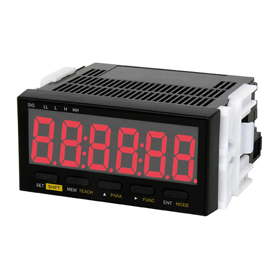
98211B
Digital Tachometer
Digital Tachometer/ Elapsed timecounter/ Time width meter/ Flowmeter
Standard input series
DT-501X/DT-501F
Instruction Manual
Thank you for purchasing SHIMPO's Digital Tachometer DT-501X/
DT-501F. For instruc tions on how to use this produc t properly
and optimally for a long period of time, please be sure to read this
manual thoroughly before use.
When you purchase the product with optional equipment:
Please refer to the operation manual of the optional equipment.
Before operation, maintenance and inspection, please
carefully read this instruction manual and follow it
for proper use.
Af te r re a d i n g, b e s u re to s to re t h i s m a n u a l i n a s a fe,
convenient place where operators can always refer to it easily.
Electric Shock.
Be sure to turn the power OFF when wiring as well as
inspecting the unit.
Failure to do so could result in electric shock.
DO NOT block the ventilation holes on the side of the main unit.
DO NOT put any foreign objects or materials inside the unit
through these holes.
Failure to follow this could result in abnormal heat generation
and/or malfunctions.
DO NOT touch the unit with wet (or sweaty) hands when
inspecting or for wiring.
Failure to do this could result in electric shock.
Precautions before use
!
Power
●Be sure to use the unit under the specified voltage (AC power
specifications: 85 - 264VAC / DC power specifications: 10.8 - 25.2VDC).
●Inverter power source cannot be used.
Input signal wire
●Connection wiring from sensors shall not be kept in the same or parallel conduit or
cable as the power source, power or high voltage cables. If you fail to separate the
wiring, noise may be superimposed on the signal wire, resulting in malfunctions.
●Use shielded wire for input power connections with the shortest possible metal conduit.
Terminal
●Check that the screws have not come loose due to vibrations after a certain period of time.
Operating environment
●Do not install the unit in the following places or conditions.
● ● Places exposed to direct sunlight, or places where the ambient temperature
exceeds a range of 0 - 45ºC.
● ● Places where the relative humidity percentage exceeds a range of 35 - 85%, or
places subject to condensation due to rapid change in humidity.
● ● Places subject to corrosive and/or combustible gases.
● ● Places subject to a large amount of dust, salinity, and/or ferric substance.
1.888.610.7664
● ● Places susceptible to noise (including static electricity).
Differential input series
CAUTION
!
www.calcert.com
10
15
20
5
25
0
30
Safety Requirements
Be sure to observe
Before operation, maintenance and inspection, please carefully read this instruction
manual and follow it for proper use. Please carefully read all information related to
this unit and safety, and precautions before use.
This instruction manual categorizes safety precautions as "DANGER", " WARNING",
and "CAUTION". Each of them is an important description related to safety. Be sure
to observe.
Improper use by neglecting the following
!
DANGER
precautions may result in the potential
for fire, serious injuries, and/or death.
!
WARNING
Improper use may result in serious injuries.
!
Improper use may result in minor injuries or
CAUTION
property damage.
●Limited Warranty
● We are not responsible for damages resulting from negligence through failure to
follow the instructions set out in this manual.
● We are not responsible for damages resulting from earthquake and/or fire unrelated
to us, actions by third parties, or any other accidents, intentional or through
customer negligence, as well as from accidents caused by misuse or improper use
under abnormal conditions.
● For information regarding assurance provisions, please read the attached warranty
certificate.
INDEX
1. Installation to the Start of Operation
2. Unit Model
3. Specifications
4. Component Part Names and Functions
5. External Dimensions
6. Installation to the Panel
7. Wiring to Power Source and Sensors (DT-501XA/DT-501XD)
8. Wiring to Power Source and Sensors (DT-501FA)
9. Basic Setting Procedure
10. Keys to be Used for Various Settings and Their Applications
11. Teaching Function Settings
12. About Mode
13. When You Select Mode 1 (Digital Tachometer Mode) for Measurement
14. When You Select Mode 2 (Elapsed Timecounter Mode) for Measurement
15. When You Select Mode 3 (Time Width Meter Mode) for Measurement
16. When You Select Mode 4 (Flowmeter Mode) for Measurement
17. Setting Method of Functions (Excluding in the Test Mode, Common in Each Mode)
18. Comparator Function
19. Memory Function
20. Test Mode (Function to Check if the Unit is Operating Normally)
21. Error Display
22. Parameter List
23. Function List
24. Option -FVT/-FVC
25. Option -BCD
26. Option -TRT
27. Option -CPT
28. DT-501X / DT-501F series model list
1
sales@calcert.com
2
2
3
3
4
4
5
6
6
6
7
8
8
10
12
14
16
17
18
19
19
20
21
23
25
27
27
28
Advertisement
Table of Contents

Related Manuals for Nidec DT-501X


Summary of Contents for Nidec DT-501X
-
Page 1: Table Of Contents
Improper use may result in minor injuries or CAUTION property damage. Thank you for purchasing SHIMPO's Digital Tachometer DT-501X/ DT-501F. For instruc tions on how to use this produc t properly ●Limited Warranty and optimally for a long period of time, please be sure to read this ●... -
Page 2: Installation To The Start Of Operation
●1. Installation to the Start of Operation This unit is designed for use according to your measurement purposes. Before use, follow the procedures below from installation to the start of operation. Check before use Connection with the Check before use p.2 - 4 Installation to the panel p.5 - 6... -
Page 3: Specifications
●3. Specifications Unit model DT-501X ● DT-501F Action mode Digital tachometer mode Flowmeter mode Elapsed timecounter mode Time width meter mode 0 - 999999 0:00:00 - 0:59:59 0:00:00 - 9:59:59 Display 1 6 digits Display (Hour:Minute:Second / base 60 display) -
Page 4: External Dimensions
●5. External Dimensions ●mm● ●6. Installation to the Panel Mount this unit to the panel according to the following procedures. Check that the mounting panel is thick enough (1.0 - 5mm) before mounting operation. Attach the provided waterproof gasket to the panel surface. * If waterproofing is not necessary, skip this step. -
Page 5: Wiring To Power Source And Sensors (Dt-501Xa/Dt-501Xd)
●7. Wiring to Power Source and Sensors (DT-501XA/DT-501XD) Note) In order to prevent electric shock, be sure to turn the power OFF. Be sure to use the unit under the rated voltage (AC power specifications: 85 - 264VAC / DC power specifications: 10.8 - 25.2VDC). The inverter output (output to connect a motor) cannot be used as power. Connection wiring from sensors shall not be kept in the same or parallel conduit or cable as the power source, power or high voltage cables. -
Page 6: Wiring To Power Source And Sensors (Dt-501Fa)
●8. Wiring to Power Source and Sensors (DT-501FA) Note) In order to prevent electric shock, be sure to turn the power OFF. Be sure to use the unit under the rated voltage (AC power specifications: 85 - 264VAC). The inverter output (output to connect a motor) cannot be used as power. Connection wiring from sensors shall not be kept in the same or parallel conduit or cable as the power source, power or high voltage cables. -
Page 7: Teaching Function Settings
●11.Teaching Function Settings When you can check (measure) the actual revolution speed, the following simple method (teaching function) can be used. The teaching function requires no complicated calculation. ● The teaching function is supported only in mode 1 and mode 4. Mode 2 and mode 3 have no teaching function. ●... -
Page 8: About Mode
●12. About Mode DT-501X/DT-501F have five modes (functions) which can be selected according to the measurement purpose. Mode Page No. Mode description Details for the setting method Digital Tachometer Mode* Digital tachometer / used as speedmeter●Displays the proportional value to the input p.8 - 9... - Page 9 ● Mode 1 (digital tachometer mode) Display value calculation equation Mode 1 Display value calculation External input pulse (Hz) P1 Pulse count per revolution Parameter setting P2 Revolution speed in the detection section(rpm) P3 Value to be displayed Equation ●(A/B) (D/C) •...
-
Page 10: When You Select Mode 2 (Elapsed Timecounter Mode) For Measurement
When You Select Mode 2 (Elapsed Timecounter Mode) for Measurement Elapsed timecounter mode Setting Method Set each setting item for mode and parameter according to the following procedures. (For the setting method of functions, refer to pages 16 and 17.) ●... - Page 11 ●Start setting according to the setting example on the previous page. The main display shows “0:00”. Normal display 0: 0 0 P r e s s a n d h o l d t h e S H I F T + To the parameter settings 0 2 - P 0 1 PA R A k e y s f o r 5 s e c o n d s o r...
-
Page 12: When You Select Mode 3 (Time Width Meter Mode) For Measurement
When You Select Mode 3 (Time Width Meter Mode) for Measurement Time wide meter mode Setting Method Set each setting item for mode and parameter according to the following procedures. (For the setting method of functions, refer to pages 16 and 17.) ●... - Page 13 • Start setting according to the setting example on the previous page. Normal display The main display shows “0:00”. 0: 0 0 P r e s s a n d h o l d t h e S H I F T + To the parameter settings 0 3 - P 0 1 PA R A k e y s f o r 5 s e c o n d s o r...
-
Page 14: When You Select Mode 4 (Flowmeter Mode) For Measurement
When You Select Mode 4 (Flowmeter Mode) for Measurement Flowmeter mode Setting Method Set each setting item for mode and parameter according to the following procedures. (For the setting method of functions, refer to pages 16 and 17.) ● Setting example (For the flow display from the tank) To display the flow ( ℓ... - Page 15 • Start setting according to the setting example on the previous page. Normal display The main display shows “0:00”. 0. 0 P r e s s a n d h o l d t h e S H I F T + To the parameter settings 0 4 - P 0 1 PA R A k e y s f o r 5 s e c o n d s o r...
-
Page 16: Setting Method Of Functions (Excluding In The Test Mode, Common In Each Mode)
17. Setting Method of Functions (Excluding in the Test Mode, Common in Each Mode) The setting method of the functions is common in each mode excluding the test mode. For the lists of functions in each mode, refer to page 21. •... -
Page 17: Comparator Function
Continued from previous page Every time you press the key, the Every time you press the key, the Function 8 setting display switches as below. display switches to the next func- ● Setting example : 1 Use the ENT key to finish setting. tion. -
Page 18: Memory Function
●19. Memory Function • Key to be used for the memory function and display MAX and MIN lamps When the current displayed value i s t h e m a x i m u m o r m i n i m u m , the MAX or MIN lamp lights up, respectively. -
Page 19: Test Mode (Function To Check If The Unit Is Operating Normally)
20. Test Mode (Function to Check if the Unit is Operating Normally) Normal display Displays the measurement value. Press and hold the SHIFT + MODE keys for 5 seconds or more. Mode display 0 1 - Displays the current set mode number. Press the key to change the mode number to “99”. -
Page 20: Parameter List
22. Parameter List The following parameters can be set in each mode. Parameters in mode 1 (Digital Tachometer Mode) Setting item Description Input range Default value Pulse count per revolution Enter the pulse count per revolution for the rotary encoder, etc. 1 - 9999 P/r 1P/r Setting revolution speed... -
Page 21: Function List
23. Function List The following functions can be set in each mode. Function in mode 1 (Digital Tachometer Mode) Setting item Description Input range Default value High set point 1 value Sets the high set point 1 value 000000 - 999999 Low set point 1 value Sets the low set point 1 value 000000 - 999999... - Page 22 *3 About the minimum revolution speed (minimum flow) When you set a value larger than 1 in the function item “F7 Minimum revolution speed (minimum flow)”, the following functions can be used. ● In mode 1 and mode 2, the display value is “0” when the measurement revolution speed becomes less than the minimum revolution speed(In mode 2, the display shows “-.-.-.-.-.-.
-
Page 23: Option -Fvt/-Fvc
●24. Option -FVT/-FVC When equipped with -FVT/-FVC option, analog signal output (voltage/current) is available according to the displayed data. ● 1. Specifications for -FVT/-FVC Option Model -FVT/-FVC Current output 4 ● 20mA 0 ● 10V Select one of these Output four output options Voltage output 1 ●... - Page 24 ● 3. -FVT/-FVC Option Setting When equipped with -FVT/-FVC option, following setting options are enabled from function setting feature. Setting item Description Input range Default Set the displayed value which corresponds to Mode 1 ●000000● ● ●999999● 1000 the maximum value of each analog signal. Maximum analog Hour:Minute:Second ●_0:00:00●...
-
Page 25: Option -Bcd
●25. Option -BCD When equipped with -BCD option, Binary Coded Decimal output is possible ●1. Specifications for -BCD Option Model -BCD NPN Open collector output Output capacity 30VDC●20mA Open collector (NPN) input Load capacity : minimum 5mA Open collector input LO input 0 ●... - Page 26 ● 3. -BCD Option Setting When equipped with -BCD option, following setting options are enabled from function setting feature. Setting item Description Input range Default Set as 0 for negative logic, set as 1 for positive logic ● _ 0_ ● (Negative logic)/ BCD output logic Negative logic (decimal point output)
-
Page 27: Option -Trt
●26. Option -TRT When equipped with -TRT option, comparison result output is possible.(LL,L,GO,H,HH,ZERO) ●1. -TRT option specifications Model -TRT Output capacity 30VDC●20mA Rsidual voltage Less than 1.5V Measured value ● Low set point 2 value LL signal is ON Measured value ● Low set point 1 value L signal is ON Low set point 1 value ●... -
Page 28: Dt-501X / Dt-501F Series Model List
●28. DT-501X / DT-501F series model list This operation manual is applicable to following models. Model Option 1 Option 2 Input spec AC power type DC power type DT-501XA-FVT DT-501XD-FVT -FVT Voltage output DT-501XA-FVT-BCD DT-501XD-FVT-BCD -BCD BCDoutput DT-501XA-TRT DT-501XD-TRT DT-501XA-TRT-FVC...
Need help?
Do you have a question about the DT-501X and is the answer not in the manual?
Questions and answers