
Subscribe to Our Youtube Channel
Related Manuals for Nidec Shimpo DT-5TS


Summary of Contents for Nidec Shimpo DT-5TS
- Page 1 DT-5TXR / DT-5TS DIGITAL PANEL MOUNT TACHOMETER Instruction Manual 1.888.610.7664 www.calcert.com sales@calcert.com...
-
Page 2: Table Of Contents
Contents Standard Accessories ........... 3 Features and Benefits ..........3 Important Safety Precautions ........3 Display and Keypad............4 Rear Panel and Terminals ..........5 Set-Up................5 Power ..............5 Sensor Connection ..........5 Self-Test..............5 DT-5TXR Panel Installation............. 6 Factory Settings ............6 Parameter Settings ..........6 Function Settings ............ -
Page 3: Standard Accessories
Standard Accessories Important Safety Precautions If any damage is apparent, do not unpack the panel Confirm that the unit is turned OFF when meter. Notify the shipping carrier immediately for connecting or disconnecting the unit to a damage claim instructions. Refer to the label to confirm sensor. -
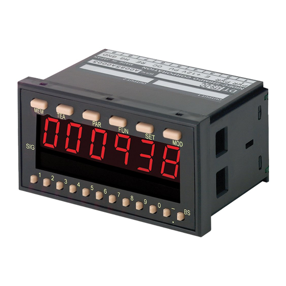
Page 4: Display And Keypad
Display and Keypad s ’ s t i Secondary Display B Secondary display Negative Sign/Decimal Point Button Negative sign setting/decimal point shift Secondary Display A Secondary display Comparator Indicator Indicates comparator condition 1.888.610.7664 www.calcert.com sales@calcert.com... -
Page 5: Rear Panel And Terminals
Rear Panel and Terminals NO. DESIGNATION Lower Module Latch Upper Module Latch Lower Module Connector Upper Module Terminal Block Rear Cover Main Terminal Block Set-Up Power Refer to diagram 1 (right) for location of the terminals. AC Models Apply 85 – 264 VAC, 50/60 Hz between terminals 1 and 2. DC Models Apply 9 –35 VDC between terminals 1 (positive) and 2 (negative) on the main terminal block. -
Page 6: Panel Installation
Panel Installation Install the DT-5TXR/DT-5TS on panel as follows: 1. Confirm that the panel thickness is 0.047” - 0.197” (1.2 mm - 5 mm). 2. Remove the two mounting adapters (provided) from the DT-5TXR/DT-5TS (diagram 2). 3. Install a water-resistant gasket on the panel (see diagram 3 & 4). 4. -
Page 7: Operation
Operation Mode Operation Selection Depending upon the type of application, the DT-5TXR/DT-5TS offers different modes of operation; these modes and their functions are: MODE -01- RPM or rate measurements -02- Elapsed time measuring / monitoring -03- Process time measurement -04- Flow rate measurement (used only in Japanese market) -99- Self-test (see “Self-Test”... - Page 8 Mode -01- (RPM or Rate Measurement) continued Set the parameters in mode -01- as follows: 7. Press the PAR button; the display will reflect: 1. Press the PAR button; the display will indicate: Parameter 4 is now showing on the primary display (1.0 second [factory setting]).
-
Page 9: Mode -02
Mode -02- (Elapsed Time Measurement/Monitoring) The following parameters must be set in mode -02- so that the DT-5TXR/DT-5TS will display the correct readings: FACTORY SETTING PARAMETER DESCRIPTION RANGE DISPLAY MEANING Pulses p i t u – _ _ 0001 1 p/r Sensing p to 99999 _ 01000... -
Page 10: Mode -03- (Process Time Measurement)
Mode -03- (Process Time Measurement) The following parameters must be set in mode -03- so that the DT-5TXR/DT-5TS will display the correct readings: FACTORY SETTING PARAMETER SETTING RANGE DISPLAY MEANING Hours, minutes, seconds 00:00:00 0:00 Hundreds of a second 0:00 0 = Trailing edge Input signal edge _ 1 _... -
Page 11: Setting High And Low Limits
Setting High and Low Limits If the variation of motor speed or time measurement is important and a “range” must be monitored, then “high” and “low” visual limits can be programmed through secondary displays A and B, respectively. Instructions to set the high and low limits: 1. -
Page 12: Memory Feature
Setting Functions (continued) Instructions to set functions are as follows: 10. Use any of the lower buttons to toggle between the three settings (see tables on page 11) for what 1. Press the FUN button; the display will indicate: the secondary displays (A and B) will show. 11. -
Page 13: Setting Examples
Setting Examples MODE -01- (RPM or Rate Measurement) Parameter 4 is selectable and is used when there is a The DT-5TXR/5TS units are fully scalable, which means that steady increase/decrease in speed and the operator wants RPM can be used to display linear speed in many units, to observe the changes (in this case higher update times i.e. - Page 14 Setting Examples (continued) MODE -03- This mode is used to measure the time a process takes from start to finish. An example could be a CNC machine that is programmed to make a certain part (push, bend, drill and stop). Need to know how much time it takes from start to finish so that future plans can be made when time comes to make several pieces of the same part.
-
Page 15: Modules Available For Dt-5Txr
Modules Available for DT-5TXR DT-5TXR with DOP-CPTR Module A variety of modules are available to provide an array of output and input options when using the DT-5TXR. DT-5TXR-CPTR The model DT-5TXR-CPTR provides three “C” type relays that Most of the modules have either a “T” or “C” suffix in can be used for setting two “set points”, one high and the part number. -
Page 16: Dop-Trtr Module
The different outputs are not achieved through DT-5TXR with DOP-TRTR Module programming, but by making the proper connections. DT-5TXR-TRTR The DT-5TXR panel meter with the DOP-TRTR The connections for the DOP-FVTR module are as follows: module provides two high set points (limits) and two low set points in addition to the normal GO signal output. - Page 17 DT-5TXR-FVTR/DT-5TXR-FVC (continued) Instructions to set the analog output characteristics are as follows: 1. Press the FUN button eleven times; the display will reflect: 5. Press the FUN button again; the display indicates: The display shows that the maximum RPM is set for The display reflects the factory setting.
-
Page 18: Dop-Bcd Module
DT-5TXR with DOP-BCD Module DT-5TXR-BCD The model DT-5TXR-BCD combination satisfies PCs and PLCs The waveforms show that when the ENABLE function is that require a BCD (parallel) signal. The DOP-BCD module LO, the BCD output data goes to a high impedance state can be configured with a negative logic output (0=HI to facilitate the selection of one unique DT-5TXR-BCD unit and 1=LO) or a positive logic output (0=LO and 1=HI),... -
Page 19: Dimensions And Specifications
DImensions and Speci cations DT-5TXR MODEL Mode e t a r e t Elapsed Time Process Time Display Range 0:00:00 - 9:59:59 0:00:00 - 0:59:59 0 - 999999 with selectable decimal point 0.00 - 999.99 s ec 0.00 - 999.99 s ec Scalable Ye s ( with outputs, s ee m odules) ±... -
Page 20: Troubleshooting
Any statements made by the Seller’s representative do not constitute warranties except to the extent that they also appear in writing. This writing constitutes the entire and final expression of the parties’ agreement. Copyright © Nidec-Shimpo America Corporation 2000. All rights reserved. Product specifications are subject to change without notice 1.888.610.7664 www.calcert.com sales@calcert.com...
Need help?
Do you have a question about the Shimpo DT-5TS and is the answer not in the manual?
Questions and answers