
Related Manuals for Nidec FG-7000TA


Summary of Contents for Nidec FG-7000TA
- Page 1 PRESENTED BY JPBOWLIN.COM 817.332.8116 J.P. Bowlin is a quality-driven Calibration Company that has provided calibration, repair and sales of all types of weighing and measurement products since 1931.
-
Page 2: Specifications
DO NOT use tools to over torque the connection adapter. Hand-tighten only so damage does not occur. SPECIFICATIONS The FG-7000TA Series digital torque gauges provide testing flex- Accuracy: ± 0.3% F.S. ibility with their external torque sensor input. Torque sensors with... - Page 3 If no load cell is connected, this symbol appears & blinks Graphic View 2. RESOLUTION TABLE Model N-cm kgf-cm lbf-ft lbf-in Interface Type Capacity FG-7000TA-1 Resolution 0.001 0.01 0.005 Capacity 3.68 44.3 Adjustable Clamp FG-7000TA-2 14.29 - 50.23 mm (0.56 - 1.98”) Resolution 0.001...
-
Page 4: Key Functions
3. KEY FUNCTIONS From the home screen, touch “MENU” to enter the main menu. (Figure 4-1) All keys are capacitive touch. ON/OFF: Push for 2 seconds to power On or Off During Measurement: Print the current force value or store data, depending on the key setting. (See 4.5.8 for key setting) In Menus: Back or quit. - Page 5 4.2.4 Test Mode Load a standard force on the gauge. Wait a moment for the Change the mode of operation between the four modes. force to stabilize. The current value (2) should equal the stan- Press “ZERO” or “MODE” keys to select. Press “LOG” to can- dard force applied.
- Page 6 4.3.2 Browse All The data will be displayed. Touch “ZERO” or “MODE” keys to shift to the next position. Touch “MENU” to see Delete or Print options. Touch “LOG” to go back. (Fig. 4-3c) Figure 4-4b Figure 4-4c 4.4.1 Print Recent Print recently stored data in this menu.
- Page 7 4.5.1 Display Mode 4.5.6 Date/Time Two display modes may be selected: Digital and Graphic (Fig- The system time may be set under this menu. Touch “ZERO” ure 4-5c). If diagram is chosen, select the diagram’s scale. to adjust the value. Press “MODE” to shift to the next position. (Figure 4-5d) Touch “LOG”...
- Page 8 4.6 Language Select between English, German and Chinese (Figure 4-6a) Figure 6-1a Figure 4-6a 6.2.1 RS232 4.8 Information The RS232 serial port is used to connect a printer to print the memory data. Information includes the model, version of the software and the serial number.
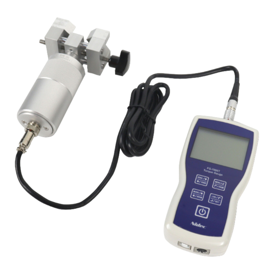
- Page 9 7.2 Diagram Sensor 160*128 Dots LCD Adapter (See LCD Screen) Connection Robust Metal Housing Capacitive Touch Keys USB Port: Recharge the internal Communications Port Ni-MH battery or (See Figure 6-1a) connect to PC 7.3 Dimensions SEALS USA, Inc. Instruments Division Tel: (630)924-7138 Email: support@seals-usa.com...
Need help?
Do you have a question about the FG-7000TA and is the answer not in the manual?
Questions and answers