Table of Contents
Advertisement
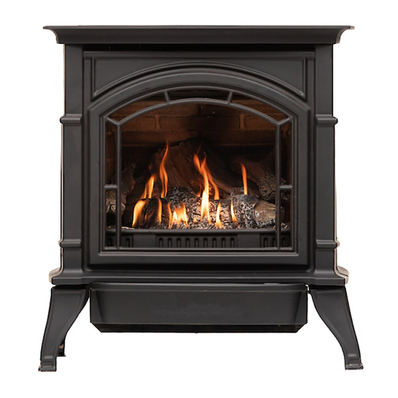
Owner's Instruction and Operation Manual
Model Number:
AG23
Report Number: F20-633
* All Pictures In This Manual Are For Illustrative Purposes Only. Actual Product May Vary.
Save These Instructions In A Safe Place For Future Reference.
Failure to follow safety warnings exactly could result in serious injury, death, or property damage.
Do not store or use gasoline or other flammable vapors and liquids in the vicinity of this or any other appliance.
WHAT TO DO IF YOU SMELL GAS:
•
Do not try to light any appliance.
•
Do not touch any electrical switch; do not use any phone in your building.
•
Leave the building immediately.
•
Immediately call your gas supplier from a neighbor's phone. Follow the gas supplier's instructions.
•
If you cannot reach your gas supplier, call the fire department.
Installation and service must be performed by a qualified installer, service agency or the gas supplier.
Please read this manual BEFORE
installing and operating this unit.
INSTALLER: Leave this manual with the appliance.
CONSUMER: Retain this manual for future reference.
THIS MANUAL IS SUBJECT TO CHANGE WITHOUT NOTICE.
© 2021 United States Stove Company, 227 Industrial Park Rd., South Pittsburg, TN 37380
R
WARNING:
FIRE OR EXPLOSION HAZARD
CALIFORNIA PROPOSITION 65 WARNING:
This product can expose you to chemicals including carbon
monoxide, which is known to the State of California to cause
cancer, birth defects, and/or other reproductive harm. For
more information, go to
853804-0502K
www.P65warnings.ca.gov
Ph. 800-750-2723
Advertisement
Table of Contents

Subscribe to Our Youtube Channel
Related Manuals for Ashley AG23


Summary of Contents for Ashley AG23
- Page 1 Owner’s Instruction and Operation Manual Model Number: AG23 Report Number: F20-633 * All Pictures In This Manual Are For Illustrative Purposes Only. Actual Product May Vary. 853804-0502K Save These Instructions In A Safe Place For Future Reference. WARNING: FIRE OR EXPLOSION HAZARD Failure to follow safety warnings exactly could result in serious injury, death, or property damage.
-
Page 2: Code Approval
CERTIFICATIONS CODE APPROVAL Direct Vent type appliances draw all combustion air from outside of the dwelling through the vent pipe. This appliance has been tested by PFS-TECO Laboratories and found to comply with the established standards for DIRECT VENT GAS FIREPLACE HEATERS in the USA and Canada as follows: STANDARDS •... -
Page 3: Installation Checklist
INSTALLATION CHECKLIST Your Gas Stove should be installed by a qualified installer only. An NFI qualified Installer can be found at www.nficertified.org/public/find-an-nfi-pro/ CUSTOMER SERVICE 1-800-750-2723 ext 5050 Text to 423-301-5624 Email to: Customerservice@usstove.com COMMISSIONING CHECKLIST This Checklist is to be completed in full by the qualified person who installs this unit. Keep this page for future reference. -
Page 4: Safety Label
SAFETY LABEL & DIMENSIONS SAFETY LABEL NOTE: This image is only an example. The label on the actual unit will vary slightly. NOTE: When initially lit, condensation will appear on the glass. This is normal and will disappear after several minutes. A paint smell will occur during the first few hours of burning. It is recommended to leave the fan off during this period to help speed the paint curing process. -
Page 5: Massachusetts Residents Only
MASSACHUSETTS RESIDENTS ONLY REQUIREMENTS FOR THE At the time of installation of the side wall horizontal vented gas fuelled equipment, the installing COMMONWEALTH OF plumber or gas fitter shall observe that a hard MASSACHUSETTS wired carbon monoxide detector with an alarm and Please read and follow these special requirements battery back-up is installed on the floor level where the gas equipment is to be installed. - Page 6 MASSACHUSETTS RESIDENTS ONLY b. Exemptions: The following equipment is exempt 2. A complete parts list for the venting system from 248 CMR 5.08(2)(a)1 through 4: design or venting system. The equipment listed in Chapter 10 entitled d. Gas Equipment - Venting System Not Provided: “Equipment Not Required To Be Vented”...
-
Page 7: Safety Information
SAFETY INFORMATION any phone in your building. WARNING: • immediately call your gas supplier from a READ THIS OWNER’S MANUAL CAREFULLY AND neighbor’s phone. Follow the gas supplier’s COMPLETELY BEFORE TRYING TO ASSEMBLE, instructions. OPERATE, OR SERVICE. ANY CHANGE TO THIS APPLIANCE OR ITS CONTROLS CAN BE 4. - Page 8 SAFETY INFORMATION 11. Keep the area around your stove clear of 18. Do not use this appliance if any part has been combustible materials, gasoline, and other underwater. Immediately call a qualified service flammable vapor and liquids. Do not run burner technician to inspect the appliance and to system where these are used or stored.
-
Page 9: Product Features
PRODUCT FEATURES PRODUCT SPECIFICATIONS • This appliance has been certified for use with either natural or propane gas. See appropriate data plates. • This appliance is not for use with solid fuels. This product was manufactured for use with natural gas. - Page 10 PRODUCT FEATURES BATTERY BOX WARNING: THIS APPLIANCE MUST BE VENTED TO THE OUTSIDE. THE VENTING SYSTEM MUST NEVER BE ATTACHED TO A CHIMNEY SERVING A SEPARATE SOLID FUEL BURNING APPLIANCE. EACH GAS APPLIANCE MUST USE A SEPARATE VENT SYSTEM. DO NOT USE COMMON VENT SYSTEMS.
-
Page 11: Clearances To Combustibles
CLEARANCES US Stove highly recommends your stove be installed by a qualified NFI (US) or WETT (Canada) technician. To find the nearest qualified installer, go to: https://nficertified.org, https://www.wettinc.ca/ CLEARANCES TO COMBUSTIBLES A Backwall to Fan Enclosure The dimensions shown in the figures are minimum B Sidewall to Stove Top Plate clearances to maintain when installing this heater. -
Page 12: Installation Information
INSTALLATION INFORMATION STOVE LOCATION • The location should be out of high traffic areas and away from furniture and draperies due to Plan for the installation of your stove. This includes heat from the appliance. determining where the unit is to be installed, the vent configuration to be used, framing and finishing •... -
Page 13: Stove Installation
STOVE INSTALLATION CHECK GAS TYPE Use proper gas type for the unit you are installing. 100 gal. (min) If you have conflicting gas type, do not install unit. Propane/LP External Supply Tank Regulator WARNING: A QUALIFIED INSTALLER OR SERVICE PERSON MUST CONNECT APPLIANCE TO GAS SUPPLY. - Page 14 STOVE INSTALLATION When using copper or flex connectors use only We recommend that you install a sediment trap/ fittings approved for gas connections. The gas drip leg in supply line as shown. Locate sediment control inlet is 3/8” NPT. trap/ drip leg where it is within reach for cleaning. Install in piping system between fuel supply and burner system.
-
Page 15: Installation Planning
VENTING INSTALLATION PLANNING WARNING: There are two basic types of direct-vent installation: TREATMENT FIRESTOPS • Horizontal Termination CONSTRUCTION OF THE CHASE MAY VARY FROM BUILDING TYPE TO BUILDING TYPE. • Vertical Termination THESE INSTRUCTIONS ARE NOT SUBSTITUTES It is important to select the proper length of vent FOR THE REQUIREMENTS OF LOCAL BUILDING pipe for the type of termination you choose. -
Page 16: Venting Requirements
VENTING NOTE: When installing in a chase, you should • Refer to the vent manufacturer’s installation insulate the chase as you would the outside walls manual for complete installation instructions. of your home. This is especially important in cold Vent installation must conform with venting climates. -
Page 17: Top Outlet Only
VENTING Vertical Vent Cap Clearance • Minimum 24 inches vertical pipe section required at unit. Refer to the “Venting Chart” section of this LOWEST DISCHARGE manual for allowable horizontal runs. OPENING • 2 inches clearance to combustibles required above APPROVED CAP horizontal pipe. -
Page 18: Wall Thickness
VENTING WALL THICKNESS vent pipe using either a wall thimble or an attic insulation shield. Follow the installation instructions The appliance vent is suitable for penetrating a supplied with the individual venting components. combustible wall assembly up to 8” in thickness. A non-combustible wall can be of any thickness up to WEATHER SEALING &... -
Page 19: Venting Installation
3. Ashley assumes no responsibility for the improper ‡ only permitted if veranda, porch, deck or balcony is fully open on a performance of the appliance when the venting system minimum 2 sides beneath the floor:... -
Page 20: Termination Clearances
VENTING INSTALLATION TERMINATION CLEARANCES Balcony - with perpendicular side wall Termination clearances buildings with with perpendicular side wall combustible and noncombustible exteriors. ALLOWABLE VENTING Inside Corner Inside Corner Combustible Combustible & 6" (152 mm) Noncombustible M = 12" (305 mm) Noncombustible P = 6”... -
Page 21: Restrictor Adjustment
VENTING INSTALLATION RESTRICTOR ADJUSTMENT DO NOT REMOVE 30° Setting Indicator WARNING: IMPROPER VENT INSTALLATION CAUSE THE BURNER FLAMES TO LIFT OR Set Position Screw “GHOST.” PERFORM A VISUAL CHECK ON FLAME APPEARANCE AFTER RESTRICTOR WARNING: ADJUSTMENT ENSURE PROPER PERFORMANCE. TO AVOID PROPERTY DAMAGE OR PERSONAL INJURY, ALLOW AMPLE TIME TO COOL BEFORE MAKING ANY ADJUSTMENTS. -
Page 22: Installation For Horizontal Termination
VENTING INSTALLATION Snorkel Restrictor Adjustment Guidelines Flame Draft Problem Solution Appearance Excessive draft Short, Adjust restrictor 12” or not enough (305 mm) flickering to close more Minimum restriction Lifting or Adjust restrictor Adequate Insufficient draft Drainage ghosting* to open more TO STOVE *If flames continue to lift or ghost after opening the restrictor and verifying correct vent installation,... -
Page 23: Horizontal Termination Configurations
VENTING INSTALLATION material such as masonry block or concrete, a Interior Wall Surface 7-1/2” [190 mm] diameter hole is acceptable). The center of the hole should line up with the Vent Cap center line of the horizontal rigid vent pipe. (Horizontal Cut a 9-1/2”... - Page 24 VENTING INSTALLATION Install Vinyl Siding Standoff Horizontal Venting Cut Vinyl Siding Away Maximum Horizontal (H) Vertical Minimum to Fit Standoff Apply Mastic 24” (610mm) 54-1/2” (1384) to All Four 20” (6m) 102-1/4” (2597mm) Sides NOTE: Add 1/4” rise per 12” horizontal length of Standoff pipe.
-
Page 25: Vertical Terminations
VENTING INSTALLATION TOP VENTING DIAGRAM VERTICAL TERMINATIONS (VERTICAL & HORIZONTAL TERMINATIONS) (A) 90° Elbow IMPORTANT: (B) Termination Cap HORIZONTAL VENT SECTIONS REQUIRE 1/4” (6 NG/LPG - 6ft (1.83m) MIN / 40ft (12.2m) MAX MM) RISE FOR EVERY 12” (305 MM) OF TRAVEL. NG/LPG - Min / Max Vertical Terminations Min Vertical Length Max Vertical Length... -
Page 26: Installation For Vertical Termination
VENTING INSTALLATION INSTALLATION FOR VERTICAL the vent pipe to combustible materials. Frame the opening as shown in this manual. TERMINATION Determine the route your vertical venting will 4. Connect a section of pipe and extend up take. If ceiling joist, roof rafters or other framing through the hole. -
Page 27: Cathedral Ceiling Installation
VENTING INSTALLATION Cathedral Ceiling Support Box Installation Roof Cathedral Flashing Ceiling Support Wall Strap 2" min. Below Finished 45° Elbows Ceiling Ceiling Firestop Offset with Wall Strap and 45° Elbows Cut Hole 1/8" Larger Than Support Box When Nails Projected Onto Roofline Firestop If area above is a room, install firestop above framed hole as shown... - Page 28 VENTING INSTALLATION VERTICAL TERMINATION Venting with Three (3) 90° Elbows CONFIGURATIONS Maximum Horizontal Minimum Vertical (V) The following three figures show the three different H + H¹ configurations for vertical termination. 24” (610 mm) 52-1/2” (1334 mm) 20” (6m) 98-3/4” (2508 mm) Vertical Rigid Venting Configuration using Three (3) 90°...
-
Page 29: Stove Installation
STOVE INSTALLATION LINER PLACEMENT LOG PLACEMENT Only the liner set that has been certified with this unit shall be used. CAUTION: STEP 1 DO NOT PLACE LOGS DIRECTLY OVER BURNER PORT HOLES. IMPROPER LOG PLACEMENT AFFECT FLAME APPEARANCE CAUSE EXCESSIVE SOOT TO BUILD UPON THE LOGS AND GLASS. -
Page 30: Safety Barrier
STOVE INSTALLATION STEP 3 STEP 6 Place dime sized pieces of ember wool on the front ports only. Do not place any of the ember wool on the back ports. The back ports will be covered by the remaining logs. STEP 7 STEP 4 SAFETY BARRIER... -
Page 31: Glass Frame Assembly
STOVE INSTALLATION 3. Use the provided latch tool to pull the spring- UNIT loaded latches out and up to release the top of FRONT the glass assembly. NOTE: Remove and store SAFETY the latch tool when not in use. BARRIER SCREEN ASH BAR GLASS FRAME ASSEMBLY... -
Page 32: Operation Information
OPERATION INFORMATION USING YOUR REMOTE CONTROL NOTE: If you do not hear any beeps when you press the sync button, contact your authorized Your remote control is preprogrammed. Ensure you dealer or installer for assistance. have installed 3 AAA batteries into your remote. 3. -
Page 33: Turn On Function
OPERATING INSTRUCTIONS TURN ON FUNCTION adjustment is not allowed in this mode. The Smart Thermostat function adjusts the flame Press the on/off button. The remote-control height in accordance to the difference between display will show all active icons on the screen. the set point temperature and the actual room 2. - Page 34 OPERATING INSTRUCTIONS IPI AND CPI MODES Flame Height: Six flame height levels are available. While the flame height icon is displayed, pressing Intermittent Pilot and Continuous (Standing) Pilot the up or down button once will increase or Features - First lights a pilot then uses the pilot decrease the flame height by 1 of 6 levels.
-
Page 35: Turning Off
OPERATING INSTRUCTIONS FIRST-TIME LIGHTING INSTRUCTIONS OPERATING INSTRUCTIONS Read the above safety information carefully before proceeding. WARNING: 2. Do not attempt to light the pilot by hand; the WHAT TO DO IF YOU SMELL GAS door must remain on this appliance during pilot •... -
Page 36: Frequently Asked Questions
Adhesives, glue, wall substrate, wall finish material, paints, and polishes are common materials that if used incorrectly will cause odor issues. Ashley is not responsible for any odor issues caused by materials © 2021 United States Stove Company... - Page 37 OPERATING INSTRUCTIONS used. If you have any additional questions or CAUTION: concerns, contact your authorized dealer or email DO NOT USE OVEN CLEANER OR AMMONIA- www.usstove.com. BASED PRODUCTS TO CLEAN GLASS. CLEAN THE GLASS ONLY WHEN IT HAS COOLED TO CAN I OPERATE DURING POWER ROOM TEMPERATURE.
- Page 38 OPERATING INSTRUCTIONS 5. Periodic visual check of the burner flame is Troubleshooting Soot required. Issue Thin black coating (soot) forms on viewing glass Flame Cause Solution Possible Causes Characteristic • Incorrect gas pressure Dark, orange Air Shutter Open venturi flame with •...
-
Page 39: Pressure Testing
OPERATING INSTRUCTIONS icon will appear on the LCD display of the remote to reignite the pilot. After pilot lights, turn on control before all battery power is lost. When the your remote to ignite. batteries are replaced, this icon will disappear. After completing these... -
Page 40: Manifold Pressure Test
OPERATING INSTRUCTIONS GAS FLAME ADJUSTMENT the tap is completely sealed. Manometer should read no pressure. During the initial installation, the air shutter opening should be checked to be certain that the shutter MANIFOLD PRESSURE TEST is set correctly as specified below. Adjustments Light pilot. -
Page 41: Troubleshooting
TROUBLESHOOTING CAUTION: INSTALLATION AND REPAIR SHALL ONLY BE DONE BY A QUALIFIED SERVICE PERSON. THE FIREPLACE SHOULD BE INSPECTED BEFORE USE BY A QUALIFIED SERVICE PERSON. IT IS REQUIRED TO BE INSPECTED AT LEAST ONCE A YEAR BY A PROFESSIONAL SERVICE PERSON. Before proceeding with the steps in the following troubleshooting guide: •... - Page 42 TROUBLESHOOTING ON/OFF rocker switch in Gas supply turned off Check OFF position Check for multiple shut-offs in the supply line. Verify gas Gas supply turned off supply is turned on. Consult with plumber or gas supplier. Low gas supply Check LP (propane) tank. Refill if necessary. Wiring disconnection or Main burner Check for faulty or incorrect wiring.
-
Page 43: Maintenance
MAINTENANCE WARNING: THE FIREPLACE AREA MUST BE KEPT CLEAR CAUTION: AND FREE FROM COMBUSTIBLE MATERIALS, LABEL ALL WIRES PRIOR TO DISCONNECTION GASOLINE AND OTHER FLAMMABLE VAPORS WHEN SERVICING CONTROLS. WIRING AND LIQUIDS. ERRORS CAUSE IMPROPER DANGEROUS OPERATION. VERIFY PROPER BURNER AND PILOT SYSTEM OPERATION AFTER SERVICING. -
Page 44: Electrical Installation
ELECTRICAL INSTALLATION ELECTRICAL SPECIFICATIONS WARNING: This appliance, when installed, must be electrically ELECTRICAL GROUNDING INSTRUCTIONS: grounded in accordance with local codes, or in the THIS APPLIANCE EQUIPPED WITH absence of local codes, with the National Electrical THREE-PRONG (GROUNDING) PLUG Code, ANSI/NFPA 70, or the Canadian Electrical YOUR PROTECTION AGAINST SHOCK HAZARD Code, CSA C22.1. -
Page 45: How To Order Repair Parts
REPLACEMENT PARTS & SERVICES OVER FIRING OF BURNER HOW TO ACCESS COMPONENTS Never “over fire” adjusting gas pressure or drilling The descriptions below show where the main out the orifice to increase Btu/hr above nameplate components are located and how to access them specifications. - Page 46 REPLACEMENT PARTS & SERVICES © 2021 United States Stove Company...
- Page 47 NOTES © 2021 United States Stove Company...
- Page 48 NOTES © 2021 United States Stove Company...
- Page 49 NOTES © 2021 United States Stove Company...
Need help?
Do you have a question about the AG23 and is the answer not in the manual?
Questions and answers