Ashley AGC500VF Owner’s Instruction And Operation Manual
Hide thumbs
Also See for AGC500VF:
- Installation and operating manual (29 pages) ,
- Owner’s instruction and operation manual (25 pages) ,
- Installation and operating manual (25 pages)
Table of Contents
Advertisement
Quick Links
Owner's Instruction and Operation Manual
Model Number:
AGC500VF
Control #:4002719
Certified for installations in the USA
Approved for installation in mobile homes
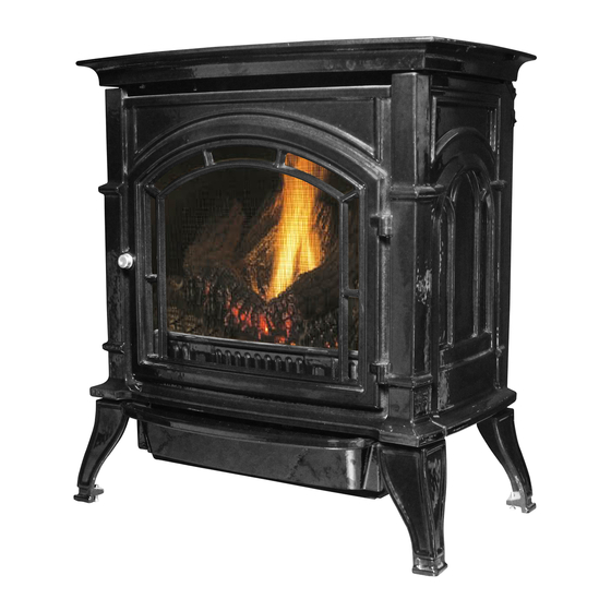
* All Pictures In This Manual Are For Illustrative Purposes Only. Actual Product May Vary.
Save These Instructions In A Safe Place For Future Reference.
Failure to follow safety warnings exactly could result in serious injury, death, or property damage.
Do not store or use gasoline or other flammable vapors and liquids in the vicinity of this or any other appliance.
WHAT TO DO IF YOU SMELL GAS:
•
Do not try to light any appliance.
•
Do not touch any electrical switch; do not use any phone in your building.
•
Leave the building immediately.
•
Immediately call your gas supplier from a neighbor's phone. Follow the gas supplier's instructions.
•
If you cannot reach your gas supplier, call the fire department.
Installation and service must be performed by a qualified installer, service agency or the gas supplier.
Please read this manual BEFORE
installing and operating this unit.
INSTALLER: Leave this manual with the appliance.
CONSUMER: Retain this manual for future reference.
THIS MANUAL IS SUBJECT TO CHANGE WITHOUT NOTICE.
© 2020 United States Stove Company, 227 Industrial Park Rd., South Pittsburg, TN 37380
WARNING:
FIRE OR EXPLOSION HAZARD
CALIFORNIA PROPOSITION 65 WARNING:
This product can expose you to chemicals including carbon
monoxide, which is known to the State of California to cause
cancer, birth defects, and/or other reproductive harm. For
more information, go to
852404G-1803K
www.P65warnings.ca.gov
Ph. 800-750-2723
Advertisement
Table of Contents

Subscribe to Our Youtube Channel
Related Manuals for Ashley AGC500VF


Summary of Contents for Ashley AGC500VF
- Page 1 Owner’s Instruction and Operation Manual Model Number: AGC500VF Control #:4002719 Certified for installations in the USA Approved for installation in mobile homes * All Pictures In This Manual Are For Illustrative Purposes Only. Actual Product May Vary. 852404G-1803K Save These Instructions In A Safe Place For Future Reference.
- Page 2 IMPORTANT INFORMATION CODES WARNING: FIRE,EXPLOSION, Adhere to all local codes or, in their absence, the ASPHYXIATION HAZARD latest edition of NFPA54. • IMPROPER ADJUSTMENT, ALTERATION, SERVICE, MAINTENANCE, OR INSTALLATION OF THIS HEATER OR ITS CONTROLS CAN CAUSE DEATH OR SERIOUS INJURY. •...
-
Page 3: Installation Checklist
INSTALLATION CHECKLIST Your Gas Stove should be installed by a qualified installer only. An NFI qualified Installer can be found at www.nficertified.org/public/find-an-nfi-pro/ CUSTOMER SERVICE 1-800-750-2723 ext 5050 Text to 423-301-5624 Email to: Customerservice@usstove.com COMMISSIONING CHECKLIST This Checklist is to be completed in full by the qualified person who installs this unit. Keep this page for future reference. -
Page 4: Massachusetts Residents Only
MASSACHUSETTS RESIDENTS ONLY REQUIREMENTS FOR THE the next adjacent floor level. In the event that the requirements of this subdivision can not be met at COMMONWEALTH OF the time of completion of installation, the owner MASSACHUSETTS shall have a period of thirty (30) days to comply This product must be installed by a licensed with the above requirements;... -
Page 5: Safety Information
MANUFACTURER REQUIREMENTS GAS EQUIPMENT VENTING SYSTEM side wall horizontally vented gas fueled equipment does not provide the parts for venting the flue PROVIDED gases, but identifies “special venting systems”, the When the manufacturer of Product Approved side following requirements shall be satisfied by the wall horizontally vented gas equipment provides manufacturer: a venting system design or venting system... - Page 6 SAFETY INFORMATION 14. Caution: Candles, incense, oil lamps, etc. they are burned off during the initial operation produce combustion by-products including of the appliance; possibly causing headaches soot. Vent-free appliances will not filter or clean or eye or lung irritation. This is a normal and soot produced by these types of products.
-
Page 7: Product Features
PRODUCT FEATURES supply pressure to a maximum of 13.0” w.c. for LP On/Off Switch systems. IGNITION CONTROLS Piezo ignitor allows ignition of the pilot without the use of matches. Millivolt control has four (4) positions: All gas to the burner is shut off at the valve. -
Page 8: Getting Started
GETTING STARTED • Sediment trap (recommended) CAUTION: • Pipe wrench GLOVES RECOMMENDED WHEN HANDLING CERAMIC FIBER LOGS TO PREVENT • Pipe sealant approved for use with propane/LPG SKIN IRRITATION FROM LOOSE FIBERS. LOGS (resistant to sulfur compounds) ARE FRAGILE — HANDLE WITH CARE. •... -
Page 9: Clearances And Height Requirements
CLEARANCES & HEIGHT REQUIREMENTS WARNING: THE DIMENSIONS SHOWN ARE MINIMUM CLEARANCES TO MAINTAIN IN INSTALLING THIS HEATER. LEFT AND RIGHT CLEARANCES ARE DETERMINED WHEN FACING THE FRONT OF THE HEATER. FOLLOW THESE INSTRUCTIONS CAREFULLY TO ENSURE SAFE INSTALLATION. FAILURE TO FOLLOW INSTRUCTIONS EXACTLY CAN CREATE A FIRE HAZARD. -
Page 10: Installation
CLEARANCES & HEIGHT REQUIREMENTS Alcove Minimum Dimensions Height From Width Depth Hearth 52” 34” 36” NOTE: Maintain minimum side and back clearances when placing stove in alcove. ATTENTION: MAINTAIN LISTED CLEARANCES FOR ANY REQUIRED SERVICING AND FOR PROPER OPERATION OF THIS APPLIANCE. INSTALLATION 2. - Page 11 INSTALLATION 3. Lift up on the front of the stove. Pivot the 5. Remove the log box from inside the unit. Lift bottom out towards you. Pull down to remove the unit off the pallet. NOTE: Make sure to lift front.
-
Page 12: Connect Gas Line
CONNECT GAS LINE NOTICE: A qualified gas appliance installer must WARNING: connect the heater to the gas supply. Consult all USE NEW BLACK IRON OR STEEL PIPE. local codes. INTERNALLY TINNED COPPER OR COPPER IMPORTANT: Hold heater valve firmly with a TUBING CAN BE USED PER NATIONAL FUEL wrench to prevent movement when connecting CODE, SECTION 2.6.3, PROVIDING GAS MEETS... - Page 13 ELECTRICAL WIRING (MILLIVOLT) B. Thermopile Output Reading Check (“B” Reading within minimum and maximum on data plate, - Thermostat contacts open - Main burner off) then check pilot voltage, 325 millivolts minimum. If the minimum millivolt reading is not obtainable, •...
-
Page 14: Log Placement
LOG PLACEMENT To install the back log (#1), position on rear log WARNING: support bracket and then press down over POSITIONING OF THE LOGS IS CRITICAL TO THE studs. SAFE AND CLEAN OPERATION OF THIS HEATER. SOOTING AND OTHER PROBLEMS MAY RESULT Right Top Right Top Right Top... -
Page 15: Flame Appearance
Log Support Bracket Studs LOG PLACEMENT Burner Ports Right Log Support Bracket Right Top Right Top Right Top Log #5 Log #5 Log #5 3. Install right bottom log (#3) on right log support CAUTION: bracket in front of back log. Right Top DURING INITIAL OPERATION OF THE NEW Log #5... -
Page 16: Millivolt Control
Thermocouple LOG PLACEMENT for LP Thermocouple for LP MILLIVOLT CONTROL Thermocouple for Natural Thermocouple for Natural PI LO Thermocouple for LP Thermocouple O FF for LP BURNER FLAME In normal operation at full rate after 15 minutes, the Thermocouple for Natural following flame appearances should be observed: The left and right rear flames should be yellow and extend 1”- 2”... - Page 17 OPERATION • Immediately call your gas supplier from a With the control knob pushed in, push in and neighbor’s phone. Follow the gas supplier’s release the pieso ignitor button to light the pilot. instructions. P IL 8. Continue pushing the control knob in for a Piezo If you cannot reach your gas supplier, call the fire further (60) sixty seconds to prevent the flame...
-
Page 18: Manual Lighting Instructions
OPERATION MANUAL LIGHTING INSTRUCTIONS Periodic Cleaning - See parts diagram for location of items discussed below. Open stove door. Remove any items necessary for easy access to the pilot (for example: logs, • Do not use cleaning fluid to clean logs or any part screens, etc.). -
Page 19: Troubleshooting
TROUBLESHOOTING WARNING: TURN THE APPLIANCE “OFF” AND ALLOW TO COOL BEFORE SERVICING. ONLY A QUALIFIED SERVICE PERSON SHOULD SERVICE AND REPAIR THE HEATER. PROBLEM POSSIBLE CAUSE REMEDY Ignitor electrode positioned Replace ignitor. wrong. Ignitor electrode is broken. Replace ignitor. Ignitor electrode not When the ignitor connected to the ignitor Reconnect ignitor cable. - Page 20 TROUBLESHOOTING WARNING: IF THE GAS QUALITY IS BAD, YOUR PILOT MAY NOT STAY LIT, THE BURNERS MAY PRODUCE SOOT AND THE HEATER MAY BACKFIRE WHEN LIT. IF THE GAS QUALITY OR PRESSURE IS LOW, CONTACT YOUR LOCAL GAS SUPPLIER IMMEDIATELY. PROBLEM POSSIBLE CAUSE REMEDY...
-
Page 21: Replacement Parts
REPLACEMENT PARTS © 2021 United States Stove Company... - Page 22 REPLACEMENT PARTS Part # Description 40861 VF Grate 40860 VF Top 40857 Left Side 40856 Right Side 27225 Side Log Retainer 27222 Rear Log Support C42373 Rocker Switch 892537.13 Base Assembly 892537.7 Control Panel 892537.8 Control Cover 40854 610120 Front Screen Assy 40859 Ash Bar 40858...
-
Page 23: Service Record
SERVICE RECORD It is recommended that your heating system is serviced regularly and that the appropriate Service Interval Record is completed. SERVICE PROVIDER Before completing the appropriate Service Record below, please ensure you have carried out the service as described in the manufacturer’s instructions. Always use the manufacturer's specified spare part when replacement is necessary. - Page 24 NOTES © 2021 United States Stove Company...
Need help?
Do you have a question about the AGC500VF and is the answer not in the manual?
Questions and answers