Advertisement
Available languages
Available languages
Quick Links
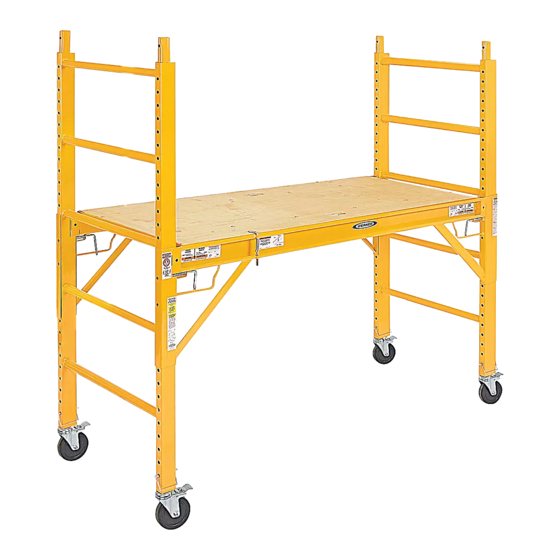
H-3797
6' STEEL ROLLING
SCAFFOLD
B
A
D
NOTE: Identify all components according to
chart above. If any components are missing or
damaged, contact Uline Customer Service.
1. Attach each side brace (C) to end frames (A) at the
desired platform height. Be sure the locking pins on
each side brace are fully locked in the end frame at
all 4 locations. (See Figure 1)
2. Install platform (B) so that it is fully seated and level
in both side braces (C) Be sure the deck pins are in
the engaged position. (See Figure 2)
3. Install 4 casters (E) into both end frames (A) and
secure with snap pins (D). (See Figure 3)
WARNING! Side braces must be level and
locked before using. All 4 casters must be
locked before use. Follow all applicable ANSI
and OSHA guidelines along with state and
local codes for use of the product.
PAGE 1 OF 6
1-800-295-5510
uline.com
PARTS FOR BASE UNIT
C
E
ASSEMBLY INSTRUCTIONS FOR BASE UNIT
Pour le français, consulter les pages 5-6.
#
DESCRIPTION
A
End Frame
B
Platform
C
Side Brace
D
Snap Pin
E
5" Caster
Figure 1
Figure 2
Disengaged
Engaged
Para Español, vea páginas 3-4.
QTY.
2
1
2
4
4
Unlocked
Locked
Figure 3
Unlocked
Locked
0521 IH-3797
Advertisement

Related Manuals for U-Line H-3797


Summary of Contents for U-Line H-3797
- Page 1 Para Español, vea páginas 3-4. Pour le français, consulter les pages 5-6. H-3797 1-800-295-5510 uline.com 6' STEEL ROLLING SCAFFOLD PARTS FOR BASE UNIT DESCRIPTION QTY. End Frame Platform Side Brace Snap Pin 5" Caster ASSEMBLY INSTRUCTIONS FOR BASE UNIT NOTE: Identify all components according to Figure 1 chart above.
- Page 2 PARTS FOR STACKING ADDITIONAL UNIT DESCRIPTION QTY. Guard Rail Panel/Gate Lock Pin 18" Outrigger Snap Pin 5" Caster *From additional unit. ASSEMBLY INSTRUCTIONS FOR STACKING ADDITIONAL UNIT NOTE: If the desired platform height is between Tighten 6' and 11' 6" additional unit is required. Frame WARNING! When stacking second unit, outriggers and guardrails are required.
- Page 3 H-3797 800-295-5510 uline.mx ANDAMIO RODANTE DE ACERO DE 6' PARTES PARA LA UNIDAD BASE DESCRIPCIÓN CANT. Marco de Extremo Plataforma Soporte Lateral Clavija de Presión Rueda de 5" INSTRUCCIONES DE ENSAMBLE DE LA UNIDAD BASE NOTA: Identifique todos los componentes de acuerdo con la gráfica que aparece más arriba.
- Page 4 PARTES PARA ESTIBAR UNA UNIDAD ADICIONAL DESCRIPCIÓN CANT. Panel/Barandal de Protección Clavija de Seguridad Soporte de 18" Clavija de Presión Rueda de 5" *De la unidad adicional. INSTRUCCIONES DE ENSAMBLE PARA ESTIBAR UNA UNIDAD ADICIONAL NOTA: Si la altura de plataforma deseada es de ¡ADVERTENCIA! La puerta del barandal de entre 1.83 mm (6') y 3.5 m (11' 6"), se requiere una protección debe abrirse hacia dentro por...
- Page 5 H-3797 1-800-295-5510 uline.com ÉCHAFAUDAGE EN ACIER À ROUES DE 1,8 M (6 PI) PIÈCES DE L'UNITÉ DE BASE DESCRIPTION QTÉ Cadre d’extrémité Plateforme Renfort latéral Goupille à anneau carré Roulette de 12,7 cm (5 po) INSTRUCTIONS D'ASSEMBLAGE DE L'UNITÉ DE BASE REMARQUE : Identifiez tous les composants selon...
- Page 6 PIÈCES POUR SUPERPOSER UNE UNITÉ SUPPLÉMENTAIRE DESCRIPTION QTÉ Rails/porte de protection Goupille d’arrêt Stabilisateur de 45,7 cm (18 po) Goupille à anneau carré Roulette de 12,7 cm (5 po) *De l’unité supplémentaire. INSTRUCTIONS D’ASSEMBLAGE POUR SUPERPOSER UNE UNITÉ SUPPLÉMENTAIRE REMARQUE : Si la hauteur de plateforme désirée AVERTISSEMENT! La porte des rails de protection se situe entre 1,8 m (6 pi) et 3,5 m (11,6 pi), une doit pivoter vers l’intérieur au-dessus de la...
Need help?
Do you have a question about the H-3797 and is the answer not in the manual?
Questions and answers