Cisco UCS X9508 Installation Manual
Server chassis
Hide thumbs
Also See for UCS X9508:
- Installation notes (54 pages) ,
- Installation and service manual (62 pages)
Table of Contents
Advertisement
Advertisement
Table of Contents

Related Manuals for Cisco UCS X9508


Summary of Contents for Cisco UCS X9508
- Page 1 Cisco UCS X9508 Server Chassis Installation Guide First Published: 2021-07-30 Last Modified: 2021-08-20 Americas Headquarters Cisco Systems, Inc. 170 West Tasman Drive San Jose, CA 95134-1706 http://www.cisco.com Tel: 408 526-4000 800 553-NETS (6387) Fax: 408 527-0883...
-
Page 2: Table Of Contents
Power Supplies LEDs Buttons Connectors Power Supply Configuration Non-Redundant Mode N+1 Power Supply Configuration N+2 Power Supply Configuration Grid Configuration LEDs LED Locations Interpreting LEDs C H A P T E R 2 Installation Cisco UCS X9508 Server Chassis Installation Guide... - Page 3 Contents Installation Notes and Warnings for the Cisco UCS X9508 Server Chassis Rack Requirements Airflow Considerations Earth Ground Considerations Handling the Chassis Moving Server Chassis Installation Guidelines Required Equipment Unpacking and Inspecting the Chassis Rail Installation Templates Front Install Template...
- Page 4 Installing and Removing the UCS X-Fabric Module Blank Installing an UCS X-Fabric Module Blank Removing an UCS X-Fabric Module Blank Recycling Printed Circuit Boards Recycling the UCS 9108 25G IFM PCBs Recycling the Chassis PCB Assembly (PCBA) Cisco UCS X9508 Server Chassis Installation Guide...
- Page 5 Technical Specifications KVM Cable Chassis Specifications Environmental Specifications Environmental Conditions and Power Requirement Specifications for Twinax SFP+ Transceivers Specifications for the Cisco UCS X9508 Chassis Power Supply Units Supported AC Power Cords and Plugs Australia and New Zealand Continental Europe International...
- Page 6 Contents Cisco UCS X9508 Server Chassis Installation Guide...
- Page 7 Cisco has more than 200 offices worldwide. Addresses and phone numbers are listed on the Cisco website at www.cisco.com/go/offices. Cisco and the Cisco logo are trademarks or registered trademarks of Cisco and/or its affiliates in the U.S. and other countries. To view a list of Cisco trademarks, go to this URL: https://www.cisco.com/c/en/us/about/legal/trademarks.html.
- Page 8 Cisco Bug Search Tool Cisco Bug Search Tool (BST) is a web-based tool that acts as a gateway to the Cisco bug tracking system that maintains a comprehensive list of defects and vulnerabilities in Cisco products and software. BST provides...
-
Page 9: Overview
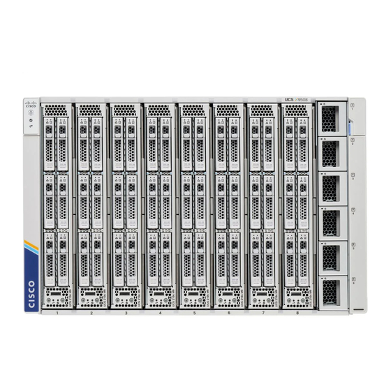
LEDs, on page 13 System Overview The Cisco UCS X9508 Server Chassis and its components are part of the Cisco Unified Computing System (UCS), which uses the Cisco UCS M6 compute node and its two Intelligent Fabric Modules (IFMs) along with the Cisco UCS Fabric Interconnects to provide advanced options and capabilities in server and data management. - Page 10 Overview System Overview Figure 1: Cisco UCS X9508 Server Chassis, Front System LEDs: Node Bays, a total of 8, which are shown • Locator LED/Button populated with UCS X210c M6 compute • System Status LED nodes. • Network Link LED...
- Page 11 Overview System Overview Figure 2: Cisco UCS X9508 Server Chassis, Rear Power Entry Modules Intelligent Fabric Modules (PEMs) for facility inlet (shown populated), which power are always deployed as a pair of the following: Each PEM contains 3 IEC 320 C20 inlets.
-
Page 12: Features And Benefits
This simplicity eliminates the need for dedicated chassis management and blade switches, reduces cabling, and enables the Cisco Unified Computing System to scale to 20 chassis without adding complexity. The Cisco UCS X9508 server chassis is a critical component in delivering the Cisco Unified Computing System benefits of data center simplicity and IT responsiveness. - Page 13 Tool-free installation Requires no specialized tools for chassis installation. Provides mounting rails for easy installation and servicing. Compute Node configurations Allows up to 8 full height UCS X210c M6 compute nodes. Cisco UCS X9508 Server Chassis Installation Guide...
-
Page 14: Chassis Components
The chassis is seven rack units (7 RU) high and can mount in an industry-standard 19-inch rack with square holes for use with cage nuts. The chassis can house up to eight full height Cisco UCS X210c M6 compute nodes. -
Page 15: Intelligent Fabric Modules
Figure 3: Cisco UCS X210c M6 Compute Node Intelligent Fabric Modules The Cisco UCS X9508 contains Intelligent Fabric Modules (IFMs) on the rear of the server chassis. IFMs have multiple functions in the server chassis: • Data traffic: IFMs support network-level communication for traditional LAN and SAN traffic as well as aggregating and disaggregating traffic to and from individual compute nodes. -
Page 16: Cisco Ucs X-Fabric Module Blanks
Cisco UCS X-Fabric Module Blanks The Cisco UCSX-9508-RBLK is Cisco UCS X-Fabric Module Blank slot which is used for providing future X-Fabric connectivity. Currently this module blank has active fans to facilitate airflow. In a typical configuration, this module blank can be installed in either of the two bottom slots in the rear of the chassis below the IFM slots. -
Page 17: Power Supplies
• Grid configuration, which is also known as N+N power supply configuration, in which N is the amount of power supplies required to support the system power requirements. Note The chassis requires a minimum of two PSUs to operate. Figure 7: AC Power Supply Cisco UCS X9508 Server Chassis Installation Guide... -
Page 18: Leds
• When connecting the chassis to facility power, make sure not to overload the capacity of a PDU or power strip, for example, by connecting all PSUs to one PDU or power strip that is not capable of carrying the total power draw of the chassis. Cisco UCS X9508 Server Chassis Installation Guide... -
Page 19: Non-Redundant Mode
If one Active power supply should fail, the surviving supplies can provide power to the chassis, until the Standby power supply can be switched to Active status. In addition, Cisco Intersight turns on any "turned-off" power supplies to bring the system back to N+1 status. The system will continue to operate, giving you a chance to replace the failed power supply. -
Page 20: N+2 Power Supply Configuration
If one or two power supplies should fail, the surviving supplies can provide power to the chassis. In addition, the Cisco Intersight interface supports turning on any "turned-off" power supplies to bring the system back to N+2 status. -
Page 21: Leds
LEDs. LED Locations The UCS X9508 server chassis uses LEDs to indicate power, status, location/identification. Other LEDs on IFMs, PSUs, fans, and compute nodes indicate status information for those elements of the system. Figure 8: LEDs on a Cisco UCS X9508 Server Chassis Front View... -
Page 22: Interpreting Leds
Overview Interpreting LEDs Figure 9: LEDs on the Cisco UCS X9508 Server Chassis Rear View Interpreting LEDs Table 2: Chassis, System Fans, and Power Supply LEDs Color Description Locator Locator not enabled. LED and button Blue Locates a selected chassis... - Page 23 No power to the chassis or the fan Fan Module module was removed from the (callout 3 on the Chassis Rear chassis. Panel) Amber Fan module restarting. Green Normal operation. Blinking amber The fan module has failed. Cisco UCS X9508 Server Chassis Installation Guide...
- Page 24 Module Fans Link down. (callout 1 and 4 the Chassis Rear Green Link up and operationally enabled. Panel) Amber Link up and administratively disabled. Blinking amber POST error or other error condition. Cisco UCS X9508 Server Chassis Installation Guide...
- Page 25 Drive Health installed, or it is not receiving power. Amber Fault detected Flashing Amber 4 Hz Rebuild drive active. If the Drive Activity LED is also flashing amber, a drive rebuild is in progress. Cisco UCS X9508 Server Chassis Installation Guide...
- Page 26 Overview Interpreting LEDs Cisco UCS X9508 Server Chassis Installation Guide...
-
Page 27: Installation
C H A P T E R Installation This chapter contains the following sections: • Installation Notes and Warnings for the Cisco UCS X9508 Server Chassis, on page 19 • Rail Installation Templates, on page 27 • Installing Cage Nuts, on page 29 •... -
Page 28: Rack Requirements
Do not use racks that have obstructions. These obstructions could impair access to field-replaceable units (FRUs). Cisco UCS is compliant with any EIA-310-D/E compliant rack. Your equipment racks must also be compliant with EIA-310-D/E standard. Also, be aware of these additional requirements: •... -
Page 29: Airflow Considerations
Ground Lug Connecting the chassis to earth ground is completed by installing a grounding bracket, assembling the ground wire and ground lug, then screwing the ground lug and ground wire to the grounding bracket. Cisco UCS X9508 Server Chassis Installation Guide... -
Page 30: Handling The Chassis
As a best practice, handle the chassis when it is empty, and use either a scissors jack or multiple people to bear the weight. The Cisco UCS X9508 has defined areas for holding the chassis (grasp points). Grasp points are not indicated on the chassis itself, but facilitate handling or moving the chassis. - Page 31 Installation Handling the Chassis Cisco UCS X9508 Server Chassis Installation Guide...
- Page 32 Handling the Chassis • Rear grasp points Note Do not lift or handle the chassis by the top rear sheet metal, as indicated by the DO NOT LIFT label on the top rear surface. Cisco UCS X9508 Server Chassis Installation Guide...
-
Page 33: Moving Server Chassis
Avoid UPS types that use ferroresonant technology. These UPS types can become unstable with systems such as the Cisco UCS, which can have substantial current draw fluctuations due to fluctuating data traffic patterns. -
Page 34: Required Equipment
Compare the shipment to the equipment list provided by your customer service representative and verify that you have received the following items: • Any printed documentation • Accessory kit, which contains: • M6 cage nut (4) • M6 x 20mmL screw (16) • Power Cable Management Arm (2), UCSX-9508-PCMA Cisco UCS X9508 Server Chassis Installation Guide... -
Page 35: Rail Installation Templates
This template shows the rack locations for mounting the front of the chassis. Align the Chassis Top of the template with the location in the rack where the top of the chassis will be and install the cage nuts and other hardware as shown. Cisco UCS X9508 Server Chassis Installation Guide... -
Page 36: Rear Install Template
This template shows the rack locations for mounting the rear of the chassis. Align the Chassis Top of the template with the location in the rack where the top of the chassis will be and install the cage nuts and other hardware as shown. Cisco UCS X9508 Server Chassis Installation Guide... -
Page 37: Installing Cage Nuts
To use the rack installation templates, go to the appropriate topic: • Front Install Template, on page 27 • Rear Install Template, on page 28 Cisco UCS X9508 Server Chassis Installation Guide... -
Page 38: Rail Kits
Verify that the cage nut is fully and correctly installed before installing the remaining cage nuts. Rail Kits The Cisco UCS X9508 supports two rail kits, Type 1 and Type 2. Each rail kit consists of two stationary rails that facilitate rack installation of the chassis and stabilize the chassis in the rack. - Page 39 Both sides must be installed in the rack to securely support the chassis. If you ordered multiple UCS X9508 chassis, you might receive both types of rail kit. For example, in a shipment of 4 chassis, the shipment might have all one type of rail kit, or a few chassis with each type of rail kit.
-
Page 40: Installing The Chassis
Note To complete the installation, the chassis must be connected to earth ground, which requires a ground lug that Cisco provides, or an equivalent. See "Ground Lug" in Earth Ground Considerations, on page Cisco UCS X9508 Server Chassis Installation Guide... -
Page 41: Installing The Rails
(Optional) Use a tape measure and level to verify that the rack rails are horizontal and at the same height. Step 6 At the front of the rack, refer to the template, then insert a screw in each front rail to secure each rail to the rack at the correct location. Cisco UCS X9508 Server Chassis Installation Guide... - Page 42 Figure 15: Secure the Rail at the Front to the Rack Step 7 At the rear of the rack, refer to the template, then insert a screw in each rear rail to secure each rail to the rack at the correct location. Cisco UCS X9508 Server Chassis Installation Guide...
-
Page 43: Rail Installation Layout
Before installing the chassis in the rack, compare the rail installation in the rack against the following layout images. If the rail installation is different than what is shown in each layout, remove the rails and reinstall them. Cisco UCS X9508 Server Chassis Installation Guide... - Page 44 Installation Rail Installation Layout Figure 17: Front Rail Layout, Both Rail Kits Cisco UCS X9508 Server Chassis Installation Guide...
-
Page 45: Installing The Top Cable Management Arms
PSUs, so the installation procedure is slightly different. See Installing the Ground Bracket and Bottom Cable Management Arms, on page Use this task to attach the cable management assemblies to the chassis before installing the chassis in the rack. Cisco UCS X9508 Server Chassis Installation Guide... - Page 46 Adjust the cable tie horizontally to align with where you wish to grasp the power cable. Step 4 You can use the cable ties to gather the power cables and secure the plugs in place. Cisco UCS X9508 Server Chassis Installation Guide...
-
Page 47: Installing The Ground Bracket And Bottom Cable Management Arms
The earth ground symbol on the side of the chassis indicates the correct location for attaching the ground bracket. b) Align the captive screws in the cable management sheetmetal with the threaded standoffs on the chassis. Cisco UCS X9508 Server Chassis Installation Guide... -
Page 48: Inserting The Chassis Into The Rack
Also, make sure to review Installation Notes and Warnings for the Cisco UCS X9508 Server Chassis, on page The chassis must be grounded by a ground lug that Cisco provides, or an equivalent. See "Ground Lug" in Earth Ground Considerations, on page... - Page 49 Removing the side trim panels exposes the screw holes in each of the front mounting brackets. Keep the side trim panels in a safe location nearby. You will replace them when the chassis is installed. Note Cisco UCS X9508 Server Chassis Installation Guide...
- Page 50 Figure 22: Detach the Chassis Side Trim Panels Step 4 At the front of the chassis, use a #3 Phillips-head screwdriver to insert and tighten the eight M6 x 20mm screws through the front mounting flanges. Cisco UCS X9508 Server Chassis Installation Guide...
-
Page 51: Installing Rear Mounting Brackets
If you will be installing the chassis in a stationary rack, continue the installation procedure. See Completing Installation, on page Installing Rear Mounting Brackets Use this procedure to install the rear mounting (tie down) brackets. Cisco UCS X9508 Server Chassis Installation Guide... - Page 52 Holding the rear mounting brackets in place, use the #3 Phillips-head screwdriver to insert the 8 M6 x 20mm screws through the rear mounting brackets, then tighten the screws to secure the rear of the chassis to the rear of the rack. Cisco UCS X9508 Server Chassis Installation Guide...
-
Page 53: Completing Installation
Figure 25: Securing the Rear of the Chassis to the Rack What to do next Complete installing the chassis into the rack. Go to Completing Installation, on page Completing Installation Continue with installing the chassis. Cisco UCS X9508 Server Chassis Installation Guide... -
Page 54: Choosing Earth Ground Option
For more information, see Connecting Rear-Mount Earth Ground, on page The facility ground cable must be terminated with the groung lug provided by Cisco, or an equivalent. For more information, see "Ground Lug" in Earth Ground Considerations, on page... - Page 55 When the chassis is fully installed, the side-mount earth ground point should be in front of the rear mounting brackets. As a result, you should have enough space to attach the ground cable. Cisco UCS X9508 Server Chassis Installation Guide...
-
Page 56: Connecting Rear-Mount Earth Ground
Connecting the chassis to facility earth ground is supported through the chassis ground bracket, which installed at the side of the bottom set of PSUs. The facility ground cable must be terminated with the ground lug provided by Cisco, or an equivalent. For more information, see "Ground Lug" in Earth Ground Considerations, on page Use this procedure to connect the chassis to earth ground. - Page 57 Align the terminal holes in the ground lug with the terminal holes in the ground bracket. c) Using a #2 Phillips screwdriver, insert and tighten two M5 x 10mm pan-head screws to secure the grounding cable to the ground bracket. Cisco UCS X9508 Server Chassis Installation Guide...
-
Page 58: Attaching Cable Management Trays
IFM cables. There are no specific cable management trays for the top and bottom of the chassis. You can use one tray for each IFM installed in the Cisco UCS X9508 server chassis but Cisco recommends that you use one tray for all IFM cables. -
Page 59: Installing The Cable Management Tray
Holding the cable management tray level, insert the hooks into the notches. c) When the cable management tray is flush against the chassis, push down to seat the hook into the notch. Cisco UCS X9508 Server Chassis Installation Guide... - Page 60 Installation Installing the Cable Management Tray Step 3 Repeat this procedure as needed to install the other cable management trays, if needed. Cisco UCS X9508 Server Chassis Installation Guide...
-
Page 61: Removing The Cable Management Tray
Detach the cable management tray from the chassis. a) At each corner of the cable management tray, apply equal pressure to slide the tray upward in the chassis notch until it can no longer slide up. Cisco UCS X9508 Server Chassis Installation Guide... - Page 62 Installation Removing the Cable Management Tray b) Holding the cable management tray level, pull it towards you to detach the tray from the chassis. Cisco UCS X9508 Server Chassis Installation Guide...
-
Page 63: Removing The Chassis From A Rack
If needed, you can order spare packaging from Cisco by using PID UCSX-9508-PKG=. If you are returning the chassis to Cisco, contact your Cisco customer service representative to arrange for return shipment to Cisco. - Page 64 Installation Repacking the Chassis Cisco UCS X9508 Server Chassis Installation Guide...
-
Page 65: Installing And Removing Components
• Recycling Printed Circuit Boards, on page 93 Components The following figure shows an empty Cisco UCS X9508 server chassis and identifies the front, back, and module slots. Note Before you remove or install components, please ensure that all software applications are shutdown and management software is in a good state. - Page 66 Installing and Removing Components Components Figure 26: View of Cisco UCS X9508 Server Chassis, Right Side The side of the chassis has no handles because the chassis is heavy, and not intended to be lifted unless you are using a scissor lift or another type of mechanical lift device to bear the weight of the chassis. The right side of the chassis has the PSU Keying Bracket which enforces proper PSU orientation as well as proper PSU type.
- Page 67 The front of the chassis accepts up to 8 Cisco UCS X210c M6 compute nodes with connections for power and basic signaling through the per-slot socket connections to the midplane. The front of the server chassis also hosts up to 6 PSUs providing power to the chassis power plane through internal connectors.
- Page 68 Installing and Removing Components Components Figure 29: View of the UCS X9508 Server Chassis, Rear View Power Entry Modules (2) IFM slots (2) Each PEM houses three IEC 320 compatible C20 power inlets inlet facility power. Fan Bays (4) Expansion Slots (2)
-
Page 69: Cisco Ucs 9108 25G Ifm Components
Only trained and qualified personnel must be allowed to install, replace, or service this equipment. Statement 1030 Cisco UCS 9108 25G IFM Components The Cisco UCS 9108 25G Intelligent Fabric Module has the following board-level components. Cisco UCS X9508 Server Chassis Installation Guide... - Page 70 Port number 5 is the left port in this group, and port number 4 is the right port group, and port number 8 is the right in the group. port in the group. IFM ejector handles, left and right Cisco UCS X9508 Server Chassis Installation Guide...
-
Page 71: Cisco Ucs X-Fabric Module Blank Components
Installing and Removing a Compute Node Blank The UCS X9508 supports up to 8 compute nodes, with a minimum configuration of one compute node. If compute node slots do not contain a compute node, you must install a compute node blank. -
Page 72: Removing A Compute Node Blank
Pull the compute node blank towards you until it is completely removed from the chassis. Notice that the module blank has indicators that show how to orient the blank. You will use this information when you install a blank. Cisco UCS X9508 Server Chassis Installation Guide... -
Page 73: Installing A Compute Node Blank
The module blank has an arrow and the word UP that show how to orient the blank. Also, if you attempt to Note install the blank with the wrong orientation, the module does not sit flush with the front of the chassis. Cisco UCS X9508 Server Chassis Installation Guide... - Page 74 Installing and Removing Components Installing a Compute Node Blank Step 3 Keeping the compute node blank vertical, slide it into the slot until the blank is flush with the face of the chassis. Cisco UCS X9508 Server Chassis Installation Guide...
-
Page 75: Installing And Removing A Compute Node
Installing and Removing a Compute Node Figure 34: Installing a Compute Node Blank Installing and Removing a Compute Node The Cisco UCS X9508 server chassis supports full-height compute nodes. For details, see the Installation and Service Note for your compute nodes. See http://www.cisco.com/en/US/products/ps10280/prod_installation_ guides_list.html... -
Page 76: Removing A Compute Node
Push the ejectors until they are parallel with the face of the compute node. When the compute node is completely installed, the retention latches at the end of each handle click into place. Removing a Compute Node Use this task to remove a compute node. Cisco UCS X9508 Server Chassis Installation Guide... - Page 77 Place your other hand underneath the compute node to support it and slide the compute node completely out of the chassis. What to do next Fill the empty compute node slot. Go to the appropriate option: • Installing a Compute Node, on page 67 • Installing a Compute Node Blank, on page 65 Cisco UCS X9508 Server Chassis Installation Guide...
-
Page 78: Installing And Removing Power Supplies
Installing a Power Supply The Cisco UCS X9508 AC PSU does not have a discrete power switch. It powers on immediately when it is successfully connected to the power midplane. PSUs can be installed in any order, and if you are installing a removed PSU, the PSU does not need to be installed in the same PSU bay that it originally occupied. - Page 79 For each PSU that must be installed, repeat these steps. Step 5 Verify the power supplies are operating by checking the power supply LEDs. See LED Locations, on page 13 Interpreting LEDs, on page Cisco UCS X9508 Server Chassis Installation Guide...
-
Page 80: Removing A Power Supply
Removing a Power Supply Caution If you are using the Cisco UCS X9508 server chassis with one power supply, which is a non-redundant power configuration. Removing the power supply will cause the compute nodes and chassis to shut down. If you are... -
Page 81: Replacing A Psu Blank
Removing a PSU Blank Use this procedure to remove a PSU blank. Note The PSU blank is a small plastic piece. It does not have a locking latch, so it slides out easily. Cisco UCS X9508 Server Chassis Installation Guide... - Page 82 Using your thumb, grasp the PSU blank by the vertical fingerhold and pull the PSU blank straight towards you. The PSU should easily slide out of the chassis. Figure 38: Removing a PSU Blank Cisco UCS X9508 Server Chassis Installation Guide...
-
Page 83: Installing A Psu Blank
Installing a PSU Blank, on page Installing a PSU Blank The minimum supported power configuration for the UCS X9508 server chassis is three PSUs. If you will be operating the server chassis with an empty PSU bay, it must be covered with a PSU blank (UCSX-9508-PSUBK). -
Page 84: Replacing The Psu Keying Bracket
Make sure to follow all safety requirements while uninstalling the chassis, including using a device, such as a mechanical lift, to bear the weight of the chassis. Step 2 With the chassis in an ESD-safe work area, locate the PSU Keying bracket on the right exterior side of the chassis. Cisco UCS X9508 Server Chassis Installation Guide... -
Page 85: Installing The Psu Keying Bracket
Step 5 Keep the screws and bracket. What to do next Installing the PSU Keying Bracket, on page Installing the PSU Keying Bracket Use this task to install a PSU Keying bracket (UCSX-9508-KEY-AC=). Cisco UCS X9508 Server Chassis Installation Guide... - Page 86 Step 5 Reinstall the chassis: a) Insert the chassis into the rack. b) Reinstall the chassis components and reconnect any cables that were disconnected. For additional info, see Installing the Chassis, on page Cisco UCS X9508 Server Chassis Installation Guide...
-
Page 87: Replacing The Power Entry Modules (Pems)
Replacing the Power Entry Modules (PEMs) The Cisco UCS X9508 chassis contains two power entry modules (PEMs). Each PEM is a grouping of 3 IEC 320 compatible C20 power inlets. One PEM supports PSUs 1 through 3, and one PEM supports PSUs 4 through 6. - Page 88 Using a T10 screwdriver, tighten the captive screws which are easily identifiable because they are next to the electrical ground icons on the chassis walls. a) Tighten the exterior captive screws. b) Tighten the interior captive screws. Cisco UCS X9508 Server Chassis Installation Guide...
-
Page 89: Removing The Power Entry Modules
PEM screw for the replaced PEM, not both screws as shown in the illustrations. Before you begin The power entry modules (PEMs) are connected to facility power, so you must disconnect facility power from the PEM that you will be removing. Cisco UCS X9508 Server Chassis Installation Guide... - Page 90 Using a T10 screwdriver, loosen the captive screws that attach the PEM to the chassis. The captive screws are easily identifiable because they are next to the electrical ground icons on the chassis walls. a) Loosen the exterior captive screws. b) Loosen the interior captive screws. Cisco UCS X9508 Server Chassis Installation Guide...
- Page 91 When you remove a PEM, you must replace it with another one. Do not operate the system with an empty PEM slot. What to do next Install a PEM. Go to Installing the Power Entry Modules, on page Cisco UCS X9508 Server Chassis Installation Guide...
-
Page 92: Installing And Removing A Fan Module
When the fan module is almost completely installed, you might feel some resistance. The resistance is normal, and it occurs when the connector at the rear of the fan contacts the corresponding socket inside the chassis. Cisco UCS X9508 Server Chassis Installation Guide... -
Page 93: Removing A Fan Module
Listen for the fan to power up and verify that the LED behavior is as expected. LED Locations, on page 13 Interpreting LEDs, on page Removing a Fan Module Step 1 Grasp the fan module handle and push down on the release button. Cisco UCS X9508 Server Chassis Installation Guide... - Page 94 Slide the fan module partially out of the chassis and place your hand underneath it to support it. When the fan disconnects from the midplane, it will power down. Step 3 Slide the fan completely out of the chassis, making sure to support its weight with your other hand. Cisco UCS X9508 Server Chassis Installation Guide...
-
Page 95: Installing And Removing A Rear Module's Fan
In a typical configuration, there are three fans numbered from one to three. Use the following procedures to replace a fan on a Cisco UCS X9508 module or module blank. •... -
Page 96: Installing A Fan For A Ucs Intelligent Fabric Module (Ifm) Or X-Fabric Module (Xfm) Blank
Press down evenly on the fan until it is fully seated. Make sure the fan is level while you're installing it. You will feel the fan click into place when it is correctly seated on the module or module blank. Cisco UCS X9508 Server Chassis Installation Guide... -
Page 97: Removing A Fan For A Ucs Intelligent Fabric Module (Ifm) Or X-Fabric Module (Xfm) Blank
Pull the fan straight up. This step disconnects the fan from the power connector and lifts the fan off of the board. Figure 45: Removing the Fan from a UCS X9508 Module or Module Blank What to do next Insert a fan module. Go to... -
Page 98: Installing And Removing An Intelligent Fabric Module
Installing and Removing an Intelligent Fabric Module Intelligent Fabric Modules (IFMs) install in the rear of the chassis. They are always deployed in pairs, and the minimum IFM configuration for each UCS X9508 is two. For more information, see Intelligent Fabric... -
Page 99: Removing An Intelligent Fabric Module
Slide the module about halfway out of the chassis, then place your other hand underneath the IFM to support it. Step 5 Continue sliding the IFM out of the chassis until it is completely removed. Cisco UCS X9508 Server Chassis Installation Guide... -
Page 100: Installing And Removing The Ucs X-Fabric Module Blank
This resistance is normal. It occurs when the connectors at the rear of the blank contact the socket inside the chassis. Step 3 Grasp each of the module handles, and keeping them level, arc them inward toward the chassis. Cisco UCS X9508 Server Chassis Installation Guide... -
Page 101: Removing An Ucs X-Fabric Module Blank
Installing an UCS X-Fabric Module Blank, on page 92 Recycling Printed Circuit Boards The Cisco UCS X9508 and some of its modules have printed circuit boards (PCBs) that must be disposed of in compliance with your appropriate recycling and e-waste regulations, including, but not limited to Commission Regulation (EU) 2019/424. - Page 102 Grasp each fan module cable and remove it. b) Grasp each fan module and remove it. c) Grasp the M.2 storage module and remove it. d) Grasp the light pipe and remove it. Cisco UCS X9508 Server Chassis Installation Guide...
- Page 103 Installing and Removing Components Recycling the UCS 9108 25G IFM PCBs Step 2 Remove the stiffener bracket. a) Using a T10 screwdriver, remove the M3 screws. b) Grasp the bracket and remove it. Cisco UCS X9508 Server Chassis Installation Guide...
- Page 104 Using a T8 screwdriver, remove the M3 screws on the exterior of the IFM. b) Using a T10 screwdriver, remove the M3 screws on the interior of the IFM. c) Grasp the bracket and remove it. Cisco UCS X9508 Server Chassis Installation Guide...
- Page 105 Using a T8 screwdriver, remove the M3 screw on the IFM faceplate. b) Grasp the plastic HDMI plug and remove it. c) Using an 8mm hexagonal nut driver, remove the standoffs. d) Using a T10 screwdriver, remove the M3 screws. Cisco UCS X9508 Server Chassis Installation Guide...
- Page 106 Grasp the PCBA and disconnect it from the sheet metal. Step 5 Disconnect the remaining components from the PCBA. a) Using the T10 screwdriver, remove the M3 screws for the top heatsink. Cisco UCS X9508 Server Chassis Installation Guide...
- Page 107 Recycling the UCS 9108 25G IFM PCBs b) Turn the PCBA over so that the bottom is facing up. c) Using the #1 Phillips screwdriver and remove the M2 screws. d) Using a pliers, release the four heatsink pushpins. Cisco UCS X9508 Server Chassis Installation Guide...
- Page 108 Grasp the plastic bracket for the M.2 module and remove it. g) If the top heat sink is still attached, grasp and remove it. h) Grasp the three fan baffles and remove them. i) Grasp the center heatsink and remove it. Cisco UCS X9508 Server Chassis Installation Guide...
-
Page 109: Recycling The Chassis Pcb Assembly (Pcba)
Recycling the Chassis PCB Assembly (PCBA) Each Cisco UCS X9508 chassis has a PCBA (motherboard) that is connected to the chassis midplane sheet metal. You must disconnect the PCBA from the chassis sheet metal to recycle the PCBA. Each PCBA is attached to the midplane sheet metal by 19 M4 screws. - Page 110 Step 2 On the left side of the chassis, use a T10 screwdriver to remove 14 M4 screws. Figure 49: Cisco UCS X9508 Chassis, Left Side Step 3 On the right side of the chassis, use a T10 screwdriver to remove 14 M4 screws plus the two captive M3 screws for the PEMs.
- Page 111 Recycling the Chassis PCB Assembly (PCBA) Step 4 On the top of the chassis, use a T10 screwdriver to remove the eight M4 screws. Figure 51: Cisco UCS X9508 Chassis, Top Step 5 Remove the PEMs. a) On the interior of the chassis, use the T10 screwdriver to remove the two M3 captive screws for the PEMs, which are indicated by the ground symbol ( b) When the screws are removed, grasp each PEM and remove it from the chassis.
- Page 112 Installing and Removing Components Recycling the Chassis PCB Assembly (PCBA) Step 6 Disconnect the rear bracket assembly: a) Grasp the two cables and unplug them. b) Using a T20 screwdriver, remove the four M4 screws. Cisco UCS X9508 Server Chassis Installation Guide...
- Page 113 With the rear bracket assembly removed, disconnect the PCB: a) Grasp the cable and unplug it. b) Using the T15 screwdriver, remove the 19 M4 screws, and remove the PCB from the chassis midplane sheet metal. Cisco UCS X9508 Server Chassis Installation Guide...
- Page 114 Installing and Removing Components Recycling the Chassis PCB Assembly (PCBA) Step 9 Recycle the sheet metal and motherboard in compliance with your local recycling and e-waste regulations. Cisco UCS X9508 Server Chassis Installation Guide...
-
Page 115: Technical Specifications
A P P E N D I X Technical Specifications This appendix lists the technical specifications for the Cisco UCS X9508 server chassis and includes the following sections: • KVM Cable, on page 107 • Chassis Specifications, on page 108 •... -
Page 116: Chassis Specifications
VGA (keyboard or mouse) monitor Chassis Specifications Figure 53: Chassis Dimensions Chassis Width: 17.5 in 444.5 mm) Total Chassis Length: 35.8 in (977.9 mm) Chassis Length sheetmetal only: 33.05 in (839.3 mm) Cisco UCS X9508 Server Chassis Installation Guide... - Page 117 Fully Populated UCS X9508 Chassis Approximately 400 lbs (181.43 kg) depending on models and options selected The system weight listed here is an estimate for a fully configured system and will vary depending on the devices installed. Cisco UCS X9508 Server Chassis Installation Guide...
-
Page 118: Environmental Specifications
Environmental Conditions and Power Requirement Specifications for Twinax SFP+ Transceivers Table 8: Environmental Conditions and Power Requirement for the SFP+ Transceiver Parameter Symbol Min. Max. Unit Storage temperature –40 °C Case temperature °C Module supply VCCT,R voltage Cisco UCS X9508 Server Chassis Installation Guide... -
Page 119: Specifications For The Cisco Ucs X9508 Chassis Power Supply Units
The jumper power cords, for use in racks, are available as an optional alternative to the standard power cords. The optional jumper power cords have an IEC C19 connector (such as a Cisco RP Series PEM) on the end Cisco UCS X9508 Server Chassis Installation Guide... -
Page 120: Australia And New Zealand
Only the regular power cords or jumper power cords provided with the chassis are supported. Australia and New Zealand Power Cord Part Number—CAB-AC-16A-AUS Cord Set Rating—16A, 250 VAC Figure 54: CAB-AC-16A-AUS Power Cord for the Cisco UCS X9508 Chassis Continental Europe Power Cord Part Number—CAB-AC-2800W-EU Cord Set Rating—16A, 250 VAC... -
Page 121: Israel
Technical Specifications Israel Figure 56: CAB-AC-2800W-INT Power Cord for the UCS X9508 Chassis Israel Power Cord Part Number—CAB-AC-2800W-ISRL Cord Set Rating—16A, 250 VAC Figure 57: CAB-AC-2800W-ISRL Power Cord for the UCS X9508 Chassis Japan and North America Non-Locking 200 to 240 VAC operation Power Cord Part Number—CAB-AC-2800W-US1... -
Page 122: Peoples Republic Of China
Technical Specifications Peoples Republic of China Figure 58: CAB-AC-2800W-US1 Power Cord for the UCS X9508 Chassis Locking 200 to 240 VAC Operation Power Cord Part Number—CAB-AC-C6K-TWLK Cord Set Rating—16A, 250 VAC Figure 59: CAB-AC-C6K-TWLK Power Cord for the UCS X9508 Chassis Peoples Republic of China Power Cord Part Number—CAB-AC-16A-CH... -
Page 123: Taiwan
Technical Specifications Taiwan Figure 60: CAB-AC-16A-CH Power Cord for the Cisco UCSX X9508 Chassis Taiwan Power Cord—CAB-AC-C19-TW Plug—250 VAC 16 A, C19 Length—7.5 feet / 2.3 meters Switzerland Power Cord Part Number—CAB-ACS-16 Cord Set Rating—16A, 250 VAC Figure 61: CAB-ACS-16 Power Cord for the UCS X9508 Chassis... - Page 124 Technical Specifications Switzerland Cisco UCS X9508 Server Chassis Installation Guide...
-
Page 125: Site Planning And Maintenance Records
A P P E N D I X Site Planning and Maintenance Records Note For information about how to query the chassis for configuration information, see the Cisco UCS Configuration Guide. This appendix includes the following records to use when installing the Cisco UCS server chassis: •... - Page 126 • Dedicated circuit for power supply • Dedicated (separate) circuits for redundant power supplies • UPS for power failures Grounding evaluation: • Circuit breaker size • CO ground (AC- powered systems) Cisco UCS X9508 Server Chassis Installation Guide...
-
Page 127: Contact And Site Information
Use the following worksheet to record contact and site information. Table 11: Contact and Site Information Contact person Contact phone Contact e-mail Building/site name Data center location Floor location Address (line 1) Address (line 2) Cisco UCS X9508 Server Chassis Installation Guide... -
Page 128: Chassis And Module Information
Compute Node 5 Compute Node 6 Compute Node 7 Compute Node 8 Intelligent Fabric Module-1 Intelligent Fabric Module-2 Note The serial numbers of all server chassis modules can be obtained using the Intersight management interface. Cisco UCS X9508 Server Chassis Installation Guide... -
Page 129: Fex Port Connection Record
Site Planning and Maintenance Records FEX Port Connection Record FEX Port Connection Record Table 13: Chassis FEX to Fabric Interconnect Port Connection Record Connected to Number Port Fabric Slot Port Connection Interconnect notes A or B Cisco UCS X9508 Server Chassis Installation Guide... -
Page 130: Ucs 6548 Fabric Interconnect Port Connection Record
Site Planning and Maintenance Records UCS 6548 Fabric Interconnect Port Connection Record UCS 6548 Fabric Interconnect Port Connection Record Table 14: Port Connection Record Fabric Interconnect Connected to Number Port Slot Port Connection notes Cisco UCS X9508 Server Chassis Installation Guide... - Page 131 46, 48 Intelligent Fabric Module (IFM), installing 90, 92 Intelligent Fabric Module (IFM), removing intelligent fabric module blank, removing intelligent fabric module, Cisco UCS 9108 Cisco UCS X9508 Server Chassis Installation Guide IN-1...
- Page 132 UCS X210c M6 compute node rear module fan, removing recycling, chassis PCB Assembly (PCBA) recycling, UCS 25G IFM PCB removing 72, 85 weight fan module chassis fully populated power supply width Cisco UCS X9508 Server Chassis Installation Guide IN-2...
Need help?
Do you have a question about the UCS X9508 and is the answer not in the manual?
Questions and answers