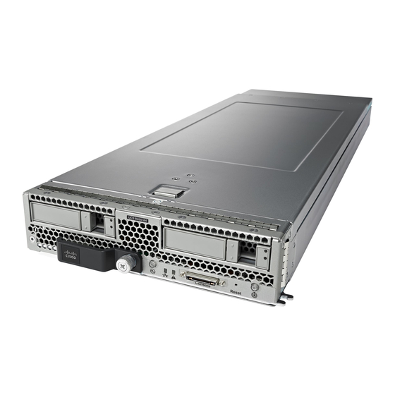
Cisco UCS B200 M4 Servicing Manual
Hide thumbs
Also See for UCS B200 M4:
- Installation and service note (30 pages) ,
- Installation and service note (46 pages) ,
- Upgrade manual (9 pages)
Table of Contents
Advertisement
Servicing a Blade Server
This chapter contains the following sections:
•
•
•
•
•
•
•
•
•
•
•
•
•
•
•
Replacing a Drive
The Cisco UCS B200 M4 blade server uses an optional Cisco UCS FlexStorage modular storage subsystem
that can provide support for two drive bays and RAID controller, or NVMe-based PCIe SSD support
functionality. If you purchased the UCS B200 M4 blade server without the modular storage system configured
as a part of the system, a pair of blanking panels may be in place. These panels should be removed before
installing hard drives, but should remain in place to ensure proper cooling and ventilation if the drive bays
are unused.
You can remove and install hard drives without removing the blade server from the chassis.
The drives supported in this blade server come with the hot-plug drive sled attached. Empty hot-plug drive
sled carriers (containing no drives) are not sold separately from the drives. A list of currently supported drives
is in the
Before upgrading or adding a drive to a running blade server, check in the service profile and make sure the
new hardware configuration will be within the parameters allowed by the service profile.
Replacing a Drive, on page 1
Removing a Blade Server Cover, on page 4
Air Baffles, on page 5
Internal Components, on page 5
Diagnostics Button and LEDs, on page 6
Installing a CMOS Battery, on page 7
Installing the FlexStorage Module, on page 8
Upgrading to Intel Xeon E5-2600 v4 CPUs, on page 9
Removing a Heat Sink and CPU, on page 10
Installing a New CPU and Heat Sink, on page 11
Installing Memory, on page 14
Installing a Virtual Interface Card Adapter, on page 17
Installing the NVIDIA M6 GPU Adapter Card, on page 19
Enabling the Trusted Platform Module, on page 22
Cisco UCS B200 M4 Blade Server Specification
Sheet.
Servicing a Blade Server
1
Advertisement
Table of Contents

Related Manuals for Cisco UCS B200 M4


Summary of Contents for Cisco UCS B200 M4
-
Page 1: Table Of Contents
Enabling the Trusted Platform Module, on page 22 Replacing a Drive The Cisco UCS B200 M4 blade server uses an optional Cisco UCS FlexStorage modular storage subsystem that can provide support for two drive bays and RAID controller, or NVMe-based PCIe SSD support functionality. - Page 2 Push the drive ejector into the closed position. You can use Cisco UCS Manager to format and configure RAID services. For details, see the Configuration Guide for the version of Cisco UCS Manager that you are using. The configuration guides are available at the following URL: http://www.cisco.com/en/US/products/ps10281/products_installation_and_configuration_guides_list.html...
- Page 3 For boot policies applied to a server with a non-Cisco VIC adapter, even if the Reboot on Boot Order Change check box is not checked, when SAN devices are added, deleted, or their order is changed, the server always reboots when boot policy changes are saved.
-
Page 4: Removing A Blade Server Cover
Press and hold the button down as shown in the figure below. Step 2 While holding the back end of the cover, pull the cover back and then up. Figure 2: Opening a Cisco UCS B200 M4 Blade Server Servicing a Blade Server... -
Page 5: Air Baffles
Figure 3: Cisco UCS B200 M4 Air Baffles Internal Components Figure 4: Inside View of the UCS B200 M4 Blade Server SD card slots Modular storage subsystem connector... -
Page 6: Diagnostics Button And Leds
At blade start-up, POST diagnostics test the CPUs, DIMMs, HDDs, and rear mezzanine modules, and any failure notifications are sent to Cisco UCS Manager. You can view these notifications in the Cisco UCS Manager System Error Log or in the output of the show tech-support command. If errors are found, an amber diagnostic LED also lights up next to the failed component. -
Page 7: Installing A Cmos Battery
Installing a CMOS Battery Installing a CMOS Battery All Cisco UCS blade servers use a CR2032 battery to preserve BIOS settings while the server is not installed in a powered-on chassis. Cisco supports the industry standard CR2032 battery that is available at most electronics stores. -
Page 8: Installing The Flexstorage Module
Figure 5: Location of the Motherboard CMOS Battery Installing the FlexStorage Module The Cisco UCS B200 M4 blade server uses an optional Cisco UCS FlexStoarge modular storage subsystem that can provide support for two drive bays and RAID controller or NVMe-based PCIe SSD support functionality. -
Page 9: Upgrading To Intel Xeon E5-2600 V4 Cpus
Release 3.1(1g) or Release 2.2(7b) Note Cisco UCS Manager Release 2.2(4) introduced a server pack feature that allows Intel E5-2600 v4 CPUs to run with Cisco UCS Manager Release 2.2(4) or later, provided that the Cisco IMC, BIOS and Capability Catalog are all running Release 2.2(7) or later. -
Page 10: Removing A Heat Sink And Cpu
CPUs by using the procedure in the following section. • If the server software or firmware is not at the required minimum version, follow the instructions in the Cisco UCS B200 M4 Server Upgrade Guide for E5-2600 v4 Series CPUs to upgrade it. Then replace the CPUs by using the procedure in the following section. -
Page 11: Installing A New Cpu And Heat Sink
• A BIOS update is available and installed that supports the CPU and the given server configuration. • The service profile for this server in Cisco UCS Manager will recognize and allow the new CPU. • The CPUs and heat sinks are different and must be installed in the correct location. The front heat sink and CPU 1 can only be installed in the front of the blade server and the rear heat sink and CPU 2 can only be installed in the rear of the blade server. - Page 12 Servicing a Blade Server Installing a New CPU and Heat Sink Figure 9: Inserting the CPU Carrier Step 2 Press gently on the top of the CPU carrier from the exterior side until it snaps into place. Step 3 Close the socket latch. Step 4 Hook the self-loading socket (SLS) lever that has the lock icon .
- Page 13 Servicing a Blade Server Installing a New CPU and Heat Sink Figure 10: Thermal Grease Application Pattern Step 7 Replace the heat sink. The yellow CPU heat sink install guide pins that are attached to the motherboard must align with the cutout on the heat sink to ensure proper installation of the heat sink. Figure 11: Replacing the Heat Sink Step 8 Tighten the four captive screws in the order shown.
-
Page 14: Installing Memory
Servicing a Blade Server Installing Memory Installing Memory To install a DIMM into the blade server, follow these steps: Procedure Step 1 Open both DIMM connector latches. Step 2 Press the DIMM into its slot evenly on both ends until it clicks into place. DIMMs are keyed. - Page 15 Servicing a Blade Server DIMMs and Channels DIMMs and Channels Each channel is identified by a letter—A, B, C, D for CPU 1, and E, F, G, H for CPU 2. Each DIMM slot is numbered 1, 2, or 3. Note that each DIMM slot 1 is blue, each slot 2 is black, and each slot 3 is off-white or beige.
- Page 16 Servicing a Blade Server Memory Performance DIMMs Per CPU CPU 1 Installed Slots CPU 2 Installed Slots A1, B1 E1, F1 A1, B1, C1 E1, F1, G1 A1, B1, C1, D1 E1, F1, G1, H1 A1, B1, C1, D1, A2, B2, C2, D2 E1, F1, G1, H1, E2, F2, G2, H2 A1, B1, C1, D1, A2, B2, C2, D2, E1, F1, G1, H1, E2, F2, G2, H2,...
-
Page 17: Installing A Virtual Interface Card Adapter
Installing a Virtual Interface Card Adapter The Cisco Virtual Interface Card (VIC) 1340 and VIC 1240 are specialized adapters that provide dual 2 x 10 Gb of Ethernet or Fiber Channel over Ethernet (FCoE) connectivity to each blade server. They plug into the dedicated VIC connector, and they are the only adapters that can be plugged into the slot 1 connector. -
Page 18: Installing An Adapter Card In Addition To The Vic Mlom Adapter
Cisco UCS B200 M4 Blade Server Specification Sheet. The UCS B200 M4 blade server has two adapter slots (Slots 1 [mLOM slot] and 2) that support the following VIC cards: • VIC 1340 and VIC 1380 •... -
Page 19: Installing The Nvidia M6 Gpu Adapter Card
Servicing a Blade Server Installing the NVIDIA M6 GPU Adapter Card information, see the firmware management chapter of one of the Cisco UCS Manager software configuration guides. Procedure Step 1 Position the adapter board connector above the motherboard connector and align the two adapter captive screws to the standoff posts on the motherboard. - Page 20 2 when the NVIDIA M6 GPU is installed. • Upgrade the Cisco UCS domain that the GPU will installed into to a version of Cisco UCS Manager that supports this card. Refer to the latest version of the Release Notes for Cisco UCS Software at the following URL for information about supported hardware: http://www.cisco.com/c/en/us/support/...
- Page 21 Position the GPU over the connector on the motherboard and align all captive screws to the standoff posts (callout 1). Step 4 Tighten the captive screws (callout 2). Figure 18: Installing the NVIDIA M6 GPU The following figure shows an NVIDIA M6 GPU installed in a Cisco UCS B200 M4 blade server. Servicing a Blade Server...
-
Page 22: Enabling The Trusted Platform Module
Servicing a Blade Server Enabling the Trusted Platform Module Figure 19: Installed NVIDIA M6 GPU Front of server Custom standoff screw What to do next After you complete the installation of the NVIDIA M6 GPU, see NVIDIA Licensing Information for information on how to download NVIDIA software and acquire the necessary NVIDIA license. - Page 23 Caution If the Cisco UCS B200 M4 server (with Intel E5-2600 v4 or v3 CPUs) is running UCS firmware that added support for Intel E5-2600 v4 CPUs, then it will work with TPM version 2.0. However, if you downgrade the firmware and BIOS to a version earlier than Release 2.2(7) or earlier than Release 3.1(1), then you are...
- Page 24 Enable TPM Support in the BIOS. If TPM support was disabled for any reason, use the following procedure to enable it. a) In the Cisco UCS Manager Navigation pane, click the Servers tab. b) On the Servers tab, expand Servers > Policies.
Need help?
Do you have a question about the UCS B200 M4 and is the answer not in the manual?
Questions and answers