Table of Contents
Advertisement
Quick Links
Advertisement
Table of Contents

Related Manuals for Cisco UCS X210c M6


Summary of Contents for Cisco UCS X210c M6
- Page 1 Cisco UCS X210c M6 Compute Node Installation and Service Note First Published: 2021-07-30 Last Modified: 2021-10-13 Americas Headquarters Cisco Systems, Inc. 170 West Tasman Drive San Jose, CA 95134-1706 http://www.cisco.com Tel: 408 526-4000 800 553-NETS (6387) Fax: 408 527-0883...
- Page 2 © 2021 Cisco Systems, Inc. All rights reserved.
-
Page 3: Table Of Contents
Removing and Installing the Compute Node Cover Removing a Compute Node Cover Installing a Compute Node Cover Internal Components Replacing a Drive NVMe SSD Requirements and Restrictions Enabling Hot Plug Support Removing a Drive Cisco UCS X210c M6 Compute Node Installation and Service Note... - Page 4 Installing a Rear Mezzanine Card in Addition to the mLOM VIC Installing a Bridge Card Servicing the Trusted Platform Module (TPM) Enabling the Trusted Platform Module Removing the Trusted Platform Module (TPM) Cisco UCS X210c M6 Compute Node Installation and Service Note...
- Page 5 Replacing a Cisco Boot-Optimized M.2 RAID Controller Recycling the PCB Assembly (PCBA) A P P E N D I X A Technical Specifications Physical Specifications for the UCS X210c M6 Compute Node Cisco UCS X210c M6 Compute Node Installation and Service Note...
- Page 6 Contents Cisco UCS X210c M6 Compute Node Installation and Service Note...
- Page 7 • Connect the equipment into an outlet on a circuit different from that to which the receiver is connected. • Consult the dealer or an experienced radio/TV technician for help. Modifications to this product not authorized by Cisco could void the FCC approval and negate your authority to operate the product.
- Page 8 Cisco has more than 200 offices worldwide. Addresses and phone numbers are listed on the Cisco website at www.cisco.com/go/offices. Cisco and the Cisco logo are trademarks or registered trademarks of Cisco and/or its affiliates in the U.S. and other countries. To view a list of Cisco trademarks, go to this URL: https://www.cisco.com/c/en/us/about/...
-
Page 9: Overview
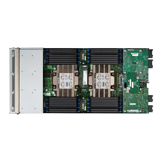
Cisco UCS X210c M6 Compute Node Overview The Cisco UCS X210c M6 is a single-slot compute node that supports two CPU sockets for Intel 3rd Generation Xeon CPUs. The compute node supports the following features with one or two identical processors installed: •... - Page 10 • Blinking amber indicates that the compute node is in a critical state, which requires attention. See System Health States, on page External Optical Connector (Oculink) that supports local console functionality. Local Console, on page Cisco UCS X210c M6 Compute Node Installation and Service Note...
-
Page 11: Front Panel Buttons
Interpreting LEDs, on page Drive Bays Each Cisco UCS X210c M6 compute node has a front mezzanine slot that can support local storage drives of different types and quantities of 2.5-inch SAS, SATA, or NVMe drives. A drive blank panel (UCSC-BBLKD-S2) must cover all empty drive bays. -
Page 12: Local Console
The connector allows a direct connection to a compute node to allow operating system installation directly rather than remotely. The connector imates to a KVM dongle cable (UCSX-C-DEBUGCBL) that provides a connection into a Cisco UCS compute node. The cable provides connection to the following: •... -
Page 13: System Health States
The following System Health LED states indicate that the compute node is not operating normally. Cisco UCS X210c M6 Compute Node Installation and Service Note... -
Page 14: Interpreting Leds
• Excessive thermal conditions Interpreting LEDs Table 1: Compute Node LEDs Color Description Compute Node Power Power off. (callout 1 on the Chassis Front Green Normal operation. Panel) Amber Standby. Cisco UCS X210c M6 Compute Node Installation and Service Note... - Page 15 Amber Fault detected Flashing Amber 4 Hz Rebuild drive active. If the Drive Activity LED is also flashing amber, a drive rebuild is in progress. Cisco UCS X210c M6 Compute Node Installation and Service Note...
- Page 16 Overview Interpreting LEDs Cisco UCS X210c M6 Compute Node Installation and Service Note...
-
Page 17: Installing A Compute Node
Compute Node Configuration, on page 14 Removing a Compute Node Blank Do not operate the Cisco UCS X9508 chassis with an empty compute node slot. Fill any empty compute node slots with either a blank or a compute node. Use this task to remove a compute node blank. -
Page 18: Installing A Compute Node Blank
1 installed compute node, so in this configuration you need 7 module blanks installed. Compute node blanks are interchangeable within the same chassis or other Cisco UCS X9508 chassis. Use this task to install a compute node blank Step 1 Grasp the blank by the finger holds. - Page 19 The module blank has indicators that show how to orient the blank. Step 3 Keeping the compute node blank vertical, slide it into the slot until the blank is flush with the face of the chassis. Cisco UCS X210c M6 Compute Node Installation and Service Note...
-
Page 20: Removing A Compute Node
Figure 4: Installing a Compute Node Blank Removing a Compute Node You must decommission the compute node using Cisco Intersight before physically removing the compute node. Do not operate the chassis with an empty compute node slot. If you will not be installing a compute node in an empty slot, install a compute node blank (UCSX-9508-FSBK) to cover the empty slot. -
Page 21: Installing A Compute Node
Step 2 Press the release button at the center of the compute node faceplate to release the ejectors. While you are inserting the compute node, keep the ejectors open. Note Cisco UCS X210c M6 Compute Node Installation and Service Note... -
Page 22: Compute Node Configuration
Compute Node Configuration, on page Compute Node Configuration Cisco UCS M6 compute nodes, such as the Cisco UCS X210c M6, can be configured and managed using the Cisco Intersight management platform in Intersight Managed Mode (Cisco Intersight Managed Mode). For... -
Page 23: Servicing A Compute Node
Removing and Installing the Compute Node Cover The top cover for the Cisco UCS X210c M6 compute node can be removed to allow access to internal components, some of which are field-replaceable. The green button on the top cover releases the compute node, so that it can be removed from the chassis. -
Page 24: Installing A Compute Node Cover
By sliding the cover back, you enable the front edge to clear the metal lip on the rear of the front mezzanine module. Installing a Compute Node Cover Use this task to install a removed top cover for the UCS X210c M6 compute node. Step 1 Insert the cover angled so that it hits the stoppers on the base. -
Page 25: Internal Components
You can remove and install some drives without removing the compute node from the chassis. All drives have front-facing access, and they can be removed and inserted by using the ejector handles. Cisco UCS X210c M6 Compute Node Installation and Service Note... -
Page 26: Nvme Ssd Requirements And Restrictions
Before upgrading or adding a drive to a running compute node, check the service profile in Cisco UCS Intersight and make sure the new hardware configuration will be within the parameters allowed by the service profile. -
Page 27: Installing A Drive
Gently slide the drive into the empty drive bay until it seats into place. Step 3 Push the drive ejector into the closed position. You should feel the ejector click into place when it is in the closed position. Cisco UCS X210c M6 Compute Node Installation and Service Note... -
Page 28: Removing A Drive Blank
The drives are front facing, so removing them does not require any disassembly. Use this procedure to remove a drive blank from the compute node. Step 1 Grasp the drive blank handle. Step 2 Slide the drive blank out of the slot. Cisco UCS X210c M6 Compute Node Installation and Service Note... -
Page 29: Installing A Drive Blank
Use this task to install a drive blank. Step 1 Align the drive blank so that the sheet metal is facing down. Step 2 Holding the blank level, slide it into the empty drive bay. Cisco UCS X210c M6 Compute Node Installation and Service Note... -
Page 30: Replacing The Front Mezzanine Module
• NVMe drives support RAID with Intel Virtual RAID on CPU (VROC) in slots 1 to 4 with direct connections to CPU 1. • The front mezzanine module also contains the SuperCap module. For information about replacing the SuperCap module, see Replacing the SuperCap Module, on page Cisco UCS X210c M6 Compute Node Installation and Service Note... -
Page 31: Front Mezzanine Module Guidelines
This step may be skipped if removing the front mezzanine blank (UCSX-X10C-FMBK). b) Using a T8 screwdriver, remove the two screws on each side of the compute node that secure the front mezzanine module to the sheet metal. Cisco UCS X210c M6 Compute Node Installation and Service Note... - Page 32 Servicing a Compute Node Removing the Front Mezzanine Module Step 3 Making sure that all the screws are removed, lift the front mezzanine module to remove it from the compute node. Cisco UCS X210c M6 Compute Node Installation and Service Note...
-
Page 33: Installing The Front Mezzanine Module
• Compute Pass Through Controller (UCSX-X10C-PT4F) • MRAID Storage Controller Module (UCSX-X10C-RAIDF) Before you begin To install the front mezzanine module, you need a T8 screwdriver and a #2 Phillips screwdriver. Cisco UCS X210c M6 Compute Node Installation and Service Note... - Page 34 Using a #2 Phillips screwdriver, tighten the captive screws on the top of the front mezzanine module. Note This step may be skipped if installing the front mezzanine blank (UCSX-X10C-FMBK). Cisco UCS X210c M6 Compute Node Installation and Service Note...
-
Page 35: Replacing The Supercap Module
RAID controller if facility power is interrupted. The front mezzanine with the SuperCap module installed is UCSX-X10C-RAIDF. Note The SuperCap module is only needed when the MRAID Storage Controller module (UCSX-C10C-RAIDF) is installed. Cisco UCS X210c M6 Compute Node Installation and Service Note... -
Page 36: Removing The Supercap Module
The SuperCap module sits in a plastic tray on the underside of the front mezzanine board. The module connects to the board through a ribbon cable with one connector to the module. Figure 8: Location of the SuperCap Module on the UCS X210c M6 Compute Node To replace the SuperCap module, follow these steps: Step 1 If you have not already removed the Front Mezzanine module, do so now. - Page 37 You might feel some resistance because the tray is curved to secure the module. Step 5 Disconnect the ribbon cable from the SuperCap module: a) On the SuperCap module, locate the lever that secures the ribbon cable to the battery pack. Cisco UCS X210c M6 Compute Node Installation and Service Note...
- Page 38 Servicing a Compute Node Removing the SuperCap Module Cisco UCS X210c M6 Compute Node Installation and Service Note...
- Page 39 Remove the existing battery pack from its case, and insert a new one, making sure to align the new battery pack so that the connector aligns with the ribbon cable. Cisco UCS X210c M6 Compute Node Installation and Service Note...
-
Page 40: Installing The Supercap Module
Installing the SuperCap Module What to do next Installing the SuperCap Module, on page 32 Installing the SuperCap Module If you removed the SuperCap module, use this procedure to reinstall and reconnect it. Cisco UCS X210c M6 Compute Node Installation and Service Note... - Page 41 When the ribbon cables are clear of the case, press the SuperCap module until it is seated in the case. You might feel some resistance as the SuperCap snaps into place. Cisco UCS X210c M6 Compute Node Installation and Service Note...
- Page 42 Align the SuperCap module with its slot on the module and seat the module into the slot. Caution Make sure not to pinch the ribbon cable while inserting the SuperCap module into the slot. Cisco UCS X210c M6 Compute Node Installation and Service Note...
-
Page 43: Replacing Cpus And Heatsinks
• The maximum number of DIMMs is 16. Only CPU1 channels A1 through H1 are used. Tools Required for CPU Replacement You need the following tools and equipment for this procedure: • T-30 Torx driver—Supplied with replacement CPU. Cisco UCS X210c M6 Compute Node Installation and Service Note... -
Page 44: Removing The Cpu And Heatsink
One cleaning kit can clean up to four CPUs. • Thermal interface material (TIM)—Syringe supplied with replacement CPU. Use only if you are reusing your existing heatsink (new heatsinks have pre-applied TIM). Can be ordered separately as Cisco PID UCS-CPU-TIM=. - Page 45 When placing the CPU on the work surface, the heatsink label should be facing up. Do not rotate the CPU assembly upside down. c) Ensure that the heatsink sits level on the work surface. Cisco UCS X210c M6 Compute Node Installation and Service Note...
- Page 46 Lower the dust cover and simultaneously press down on the edges until it snaps into place over the CPU socket. Do not press down in the center of the dust cover! Caution Cisco UCS X210c M6 Compute Node Installation and Service Note...
- Page 47 Gently pull up on the outer edge of the CPU carrier so that you can disengage the pair of CPU clips (3 in the following illustration) which are opposite the TIM breaker. f) Grasp the CPU carrier along the short edges and lift it straight up to remove it from the heatsink. Cisco UCS X210c M6 Compute Node Installation and Service Note...
- Page 48 Align the posts on the fixture and the pin 1 locations on the CPU carrier and the fixture (1 in the following illustration). d) Lower the CPU and CPU carrier onto the fixture. Cisco UCS X210c M6 Compute Node Installation and Service Note...
-
Page 49: Installing The Cpu And Heatsink
Use the provided cleaning kit (UCSX-HSCK) to remove all of the thermal interface barrier (thermal grease) from the CPU, CPU carrier, and heatsink. Make sure to use only the Cisco-provided cleaning kit, and make sure that no thermal grease is left on any Important surfaces, corners, or crevices. - Page 50 Using the syringe of TIM provided with the new CPU (UCS-CPU-TIM=), apply 1.5 cubic centimeters (1.5 ml) of thermal interface material to the top of the CPU. Use the pattern shown in the following figure to ensure even coverage. Cisco UCS X210c M6 Compute Node Installation and Service Note...
- Page 51 The heatsink is correctly oriented when the embossed triangle points to the CPU pin 1 location, as shown. Make sure the rotating wires are in the unlocked position so that the feet of the wires do not impede installing Caution the heatsink. Cisco UCS X210c M6 Compute Node Installation and Service Note...
- Page 52 Installing the CPU and Heatsink Step 5 Install the CPU assembly onto the CPU motherboard socket. a) Push the rotating wires inward to the unlocked position so that they do not obstruct installation. Cisco UCS X210c M6 Compute Node Installation and Service Note...
- Page 53 The heatsink is correctly oriented when the embossed triangle points to the CPU pin 1 location, as shown. Caution Make sure the rotating wires are in the unlocked position so that the feet of the wires do not impede installing the heatsink. Cisco UCS X210c M6 Compute Node Installation and Service Note...
- Page 54 Set the T30 Torx driver to 12 in-lb of torque and tighten the 4 securing nuts to secure the CPU to the motherboard (2). You can start with any nut, but make sure to tighten the securing nuts in a diagonal pattern. Cisco UCS X210c M6 Compute Node Installation and Service Note...
-
Page 55: Replacing Memory Dimms
Cisco UCS C220/C240/B200 M6 Memory Guide. Caution Only Cisco memory is supported. Third-party DIMMs are not tested or supported. This compute node contains 32 DIMM slots—16 per CPU Memory Considerations • All DIMMs must be all DDR4 DIMMs. - Page 56 • Channels for CPU 2 are P2 A1 and A2, P2 B1 and B2, P2 C1 and C2, P2 D1 and D2, P2 E1 and E2, P2 F1 and F2, P2 G1 and G2, P2 H1 and H2. The following illustration shows the memory slot and channel IDs. Cisco UCS X210c M6 Compute Node Installation and Service Note...
- Page 57 The table below lists recommended configurations. Using 3, 5, 7, 9, 10, 11, or 13-15 DIMMs per CPU is not recommended. Other configurations results in reduced performance. The following table shows the memory population order for DDR4 DIMMs. Cisco UCS X210c M6 Compute Node Installation and Service Note...
- Page 58 DIMM or the slot. Check the keying on the slot and verify it against the keying on the bottom of the DIMM. When the slot's key and the DIMM's notch are aligned, reinstall the DIMM. Cisco UCS X210c M6 Compute Node Installation and Service Note...
-
Page 59: Installing A Dimm Or Dimm Blank
Populate all slots with a DIMM or DIMM blank. A slot cannot be empty. Figure 10: Installing Memory Memory Performance When considering the memory configuration of the compute node, there are several things to consider. For example: Cisco UCS X210c M6 Compute Node Installation and Service Note... -
Page 60: Memory Mirroring And Ras
Intel Optane Persistent Memory Module Population Rules and Performance Guidelines This topic describes the rules and guidelines for maximum memory performance when using Intel Optane persistent memory modules (PMEMs) with DDR4 DIMMs. Cisco UCS X210c M6 Compute Node Installation and Service Note... -
Page 61: Installing Intel Optane Persistent Memory Modules
Replace the top cover to the compute node. d) Replace the compute node in the chassis. e) Wait for Cisco Intersight to complete its automatic discovery of the compute node. Step 3 Perform post-installation actions: • If the existing configuration is in 100% Memory mode, and the new PMEM is also in 100% Memory mode (the factory default), the only action is to ensure that all PMEMs are at the latest, matching firmware level. -
Page 62: Bios Setup Utility Menu For Pmem
App Direct mode without interleaving, the number of regions is equal to the number of PMEMs in the compute node. From the Regions page, you can configure memory goals that tell the PMEM how to allocate resources. • Create goal config Cisco UCS X210c M6 Compute Node Installation and Service Note... -
Page 63: Servicing The Mlom
Update Servicing the mLOM The UCS X210c M6 compute node supports a modular LOM (mLOM) card to provide additional rear-panel connectivity. The mLOM socket is on the rear corner of the motherboard. The mLOM socket provides a Gen-3 x16 PCIe lane. The socket remains powered when the compute node is in 12 V standby power mode and it supports the network communications services interface (NCSI) protocol. -
Page 64: Replacing An Mlom Card
Step 5 Tighten the captive thumbscrews to secure the card. Step 6 If your compute node has a bridge card (Cisco UCS VIC 14000 Series Bridge), reattach the bridge card. Installing a Bridge Card, on page Step 7 Replace the top cover of the compute node. -
Page 65: Servicing The Vic
Keeping the card level, lower it and press firmly to seat the card into the socket. d) Tighten the captive thumbscrews to secure the card. e) If your compute node has a bridge card (Cisco UCS VIC 14000 Series Bridge), reattach the bridge card. Installing a Bridge Card, on page f) Replace the top cover of the compute node. -
Page 66: Installing A Bridge Card
Installing an mLOM Card, on page Installing a Bridge Card The Cisco UCS VIC 14000 Series Bridge is a physical card that provides data connection between the mLOM and VIC. Use this procedure to install the bridge card. Note The bridge card installs upside down so that the connectors meet with the sockets on the MLOM and VIC. -
Page 67: Servicing The Trusted Platform Module (Tpm)
(ensuring that the platform can prove that it is what it claims to be) and attestation (a process helping to prove that a platform is trustworthy and has not been breached) are necessary steps to ensure safer computing in all Cisco UCS X210c M6 Compute Node Installation and Service Note... -
Page 68: Enabling The Trusted Platform Module
It is a requirement for the Intel Trusted Execution Technology (TXT) security feature, which must be enabled in the BIOS settings for a compute node equipped with a TPM. The UCS X210c M6 Compute Node supports the Trusted Platform Module 2.0, which is FIPS140-2 compliant (UCSX-TPM3-002=). -
Page 69: Removing The Trusted Platform Module (Tpm)
Removing and Installing the Compute Node Cover, on page Step 1 Locate the TPM module. Step 2 Using the pliers, grip the head of the screw and turn it counterclockwise until the screw releases. Cisco UCS X210c M6 Compute Node Installation and Service Note... -
Page 70: Mini Storage Module
Press out on the securing clips to disengage the module from the socket on the compute node's motherboard. b) Pull straight up on the storage module to remove it. Cisco UCS X210c M6 Compute Node Installation and Service Note... -
Page 71: Installing An M.2 Ssd Card
Angle the end with the screw into the end of the carrier that has 2 parallel guide clips. c) Press the other end of the SSD into the carrier until the alignment pins engage, and the retaining clip clicks the SSD into place. Cisco UCS X210c M6 Compute Node Installation and Service Note... -
Page 72: Replacing A Boot-Optimized M.2 Raid Controller Module
Replacing a Boot-Optimized M.2 RAID Controller Module Replacing a Boot-Optimized M.2 RAID Controller Module The Cisco Boot-Optimized M.2 RAID Controller module connects to the mini-storage module socket on the motherboard. It includes slots for two SATA M.2 drives, plus an integrated 6-Gbps SATA RAID controller that can control the SATA M.2 drives in a RAID 1 array. -
Page 73: Replacing A Cisco Boot-Optimized M.2 Raid Controller
• Hot-plug replacement is not supported. The compute node must be powered off. • Monitoring of the controller and installed SATA M.2 drives can be done using Cisco Intersight. They can also be monitored using other utilities such as UEFI HII, and Redfish. - Page 74 Install the single screw that secures the end of the M.2 SSD to the carrier. g) Turn the controller over and install the second M.2 drive. Figure 11: Cisco Boot-Optimized M.2 RAID Controller, Showing M.2 Drive Installation Step 3...
-
Page 75: Recycling The Pcb Assembly (Pcba)
Removing and Installing the Compute Node Cover, on page Step 1 (Optional) If the CPUs and heat sinks are still installed, remove them: a) Using a T30 Torx screwdriver, loosen the eight captive screws. Cisco UCS X210c M6 Compute Node Installation and Service Note... - Page 76 For each CPU, push the retaining wires toward each other (inwards) to unlock the CPU and heat sink. c) Remove each CPU from the motherboard and flip each CPU upside down. Cisco UCS X210c M6 Compute Node Installation and Service Note...
- Page 77 Use the T8 screwdriver to remove the M3 top mounting screw on each exterior side of the compute node. b) Use the #2 Phillips screwdriver to remove the two captive screws on the front mezzanine module. Cisco UCS X210c M6 Compute Node Installation and Service Note...
- Page 78 (Optional) If the rear bridge card is installed, use the #2 screwdriver to remove the two screws, then remove the card. Step 4 (Optional) If the rear mezzanine card is installed, use the #2 screwdriver to remove the four captive screws, then remove the card. Cisco UCS X210c M6 Compute Node Installation and Service Note...
- Page 79 (Optional) If the mLOM card is installed, use the #2 screwdriver to remove the four captive screws, then remove the card. Step 6 Using a T10 Torx driver, remove the two M3 screws and remove the middle M.2 module. Cisco UCS X210c M6 Compute Node Installation and Service Note...
- Page 80 Use the T8 screwdriver to remove the M3 bottom mounting screw on each exterior side of the compute node. b) Turn the compute node upside down and use the T10 screwdriver to remove the two M3 mounting screws on the bottom of the sheet metal. Cisco UCS X210c M6 Compute Node Installation and Service Note...
- Page 81 Use the #2 Phillips screwdriver to remove the front mezzanine cage retaining screw, then remove the cage. c) Use the T10 screwdriver to remove the four M3 screws. 6 mm standoffs (2) Red circles ( Cisco UCS X210c M6 Compute Node Installation and Service Note...
- Page 82 M3 screws (4) Blue circles ( Front mezzanine cage retaining screw (1) Purple circle ( Step 10 Recycle the sheet metal and motherboard in compliance with your local recycling and e-waste regulations. Cisco UCS X210c M6 Compute Node Installation and Service Note...
-
Page 83: Technical Specifications
A P P E N D I X Technical Specifications This appendix contains the following topics: • Physical Specifications for the UCS X210c M6 Compute Node, on page 75 Physical Specifications for the UCS X210c M6 Compute Node Specification Value Height 1.93 inches (49.02 mm) - Page 84 Technical Specifications Technical Specifications Cisco UCS X210c M6 Compute Node Installation and Service Note...
- Page 85 SuperCap module removing, trusted platform module (TPM) installing, compute node installing, compute node blank installing, CPU installing, drive blank installing, heatsink servicing, mLOM Cisco UCS X210c M6 Compute Node Installation and Service Note IN-1...
- Page 86 INDEX SuperCap module, installing SuperCap module, removing trusted platform module (TPM), removing Cisco UCS X210c M6 Compute Node Installation and Service Note IN-2...
Need help?
Do you have a question about the UCS X210c M6 and is the answer not in the manual?
Questions and answers