Table of Contents
Advertisement
Quick Links
Advertisement
Table of Contents

Related Manuals for Lenovo SI4091


Summary of Contents for Lenovo SI4091
- Page 1 Lenovo Flex System SI4091 10Gb System Interconnect Module Installation Guide...
- Page 2 LIMITED AND RESTRICTED RIGHTS NOTICE: If data or software is delivered pursuant a General Services Administration “GSA” contract, use, reproduction, or disclosure is subject to restrictions set forth in Contract No. GS-35F-05925. Lenovo and the Lenovo logo are trademarks of Lenovo in the United States, other countries, or both.
-
Page 3: Table Of Contents
Handling Static-Sensitive Devices ....17 Installing the SI4091 ......18 Removing or Replacing the Switch . - Page 4 People’s Republic of China Class A Electronic Emission Statement ..61 Taiwan Class A Compliance Statement ....61 SI4091 10Gb System Interconnect Module Installation Guide...
-
Page 5: Safety Information
Przed zainstalowaniem tego produktu, należy zapoznać się z książką “Informacje dotyczace bezpieczeństwa” (Safety Information). Antes de instalar este produto, leia as Informações sobre Segurança. Перед установкой продукта прочтитe инcтрyкции по тexникe безопасности. Pred inštaláciou tohto zariadenia si prečítajte Bezpečnostné predpisy. © Copyright Lenovo 2016 Safety Information... - Page 6 Antes de instalar este producto, lea la información de seguridad. Läs säkerhetsinformationen innan du installerar den här produkten. Bu ürünü kurmadan önce güvenlik bilgilerini okuyun. Youq mwngz yungh canjbinj neix gaxgonq, itdingh aeu doeg aen canjbinj soengq cungj vahgangj ancien suisik. SI4091 10Gb System Interconnect Module Installation Guide...
-
Page 7: Safety Statements
2. First, remove power cords from outlet. 3. Attach signal cables to connectors. 3. Remove signal cables from connectors. 4. Attach power cords to outlet. 4. Remove all cables from devices. 5. Turn device ON. © Copyright Lenovo 2016 Safety Information... -
Page 8: Ul Regulatory Information
Statement 25 CAUTION: This product contains a Class 1M laser. Do not view directly with optical instruments. UL Regulatory Information This device is for use only with listed Lenovo Flex System Enterprise Chassis. SI4091 10Gb System Interconnect Module Installation Guide... -
Page 9: Chapter 1. The Si4091 10Gb System Interconnect Module
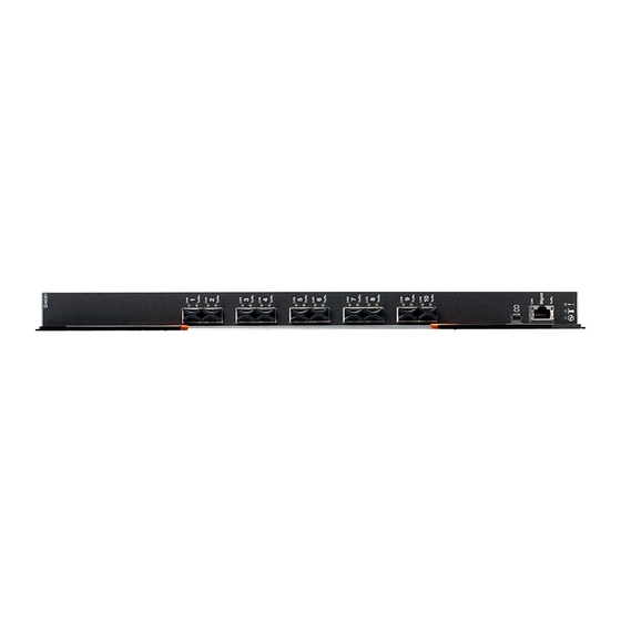
Chapter 1. The SI4091 10Gb System Interconnect Module This Installation Guide provides information about the Lenovo® Flex System™ SI4091 10Gb System Interconnect Module (referred to as SI4091 or “switch” throughout this document). Figure 1. The SI4091 SFP+ module ports RS-232 serial port... - Page 10 SFP+ ports can be populated with 10 Gb optical or copper SFP+ transceiver modules or Direct-Attach Cables (DACs), or legacy 1 Gb optical or copper SFP transceiver modules. In addition to port flexibility, you can manage and configure the SI4091 through the following interfaces: ...
-
Page 11: Documentation
About this Installation Guide This Installation Guide provides information and instructions for installing the SI4091, updating the firmware, and solving problems. For other information about configuration and management of the switch, refer to the documents described in “Related Documentation” on page Note: ... -
Page 12: Related Documentation
Command Reference for your specific switch and its installed firmware. See the documentation that came with your Lenovo chassis for information about the environmental conditions and specifications that are supported by the system. SI4091 10Gb System Interconnect Module Installation Guide... -
Page 13: Chapter 2. Installing And Removing The Si4091
A Lenovo Flex System network adapter must be installed in each compute node with which you want to communicate. To enable the switch to communicate with a compute node, at least one switch must be installed in the Lenovo Flex System chassis. For details about network adapter installation, configuration, and use, see the documentation that comes with the Lenovo Flex System network adapter. - Page 14 Note: I/O bays 1 and 2 support any standard Lenovo Flex System switch or pass-thru module. When you install an I/O network adapter in the left-most fabric connector on the compute node, these I/O bays support any switch with the same type of network interface that is used by the corresponding network adapter.
-
Page 15: Before Installing The Si4091
Attention: Product information is required in order to register your SI4091, update its firmware, place a service call, or replace the unit. Some of the product information labels may be hidden from view once the SI4091 is installed. To prevent the need to remove the switch in order to read required... -
Page 16: Installation Guidelines
You do not have to turn off the Lenovo Flex System chassis to install or replace any of the hot-swap modules on the front or rear of the Lenovo Flex System chassis. -
Page 17: System Reliability Guidelines
System Reliability Guidelines To help ensure proper cooling, performance, and system reliability, make sure that the following requirements are met: Each of the bays on the rear of the Lenovo Flex System chassis contains either a module or a filler module. -
Page 18: Installing The Si4091
4. If you have not already done so, touch the static-protective package that contains the switch to an unpainted metal surface of the Lenovo Flex System chassis or an unpainted metal surface on any other grounded rack-component for at least 2 seconds. - Page 19 DACs, cables, and the optional network devices to which the cables are connected. 13. Make sure that the data (non-management) ports on the switch are enabled through the Chassis Management Module (CMM). © Copyright Lenovo 2016 Chapter 2: Installing and Removing the SI4091...
-
Page 20: Removing Or Replacing The Switch
Removing or Replacing the Switch Note: The following illustration shows how to remove and replace the switch from the Lenovo Flex System chassis. The appearance of your Lenovo Flex System chassis might be different; see the documentation for your Lenovo Flex System chassis for additional information. -
Page 21: Connecting Switch Ports
Pin out of the mini-USB-to-RJ-45 cable is as follows: Table 2. Pin out for the included mini-USB-to-RJ-45 cable PIN # Function Direction Not connected Not connected Not connected Not connected © Copyright Lenovo 2016 Chapter 2: Installing and Removing the SI4091... -
Page 22: The Rj-45 Management Port
To connect the RJ-45 connector to the switch, push the RJ-45 cable connector into the port connector until it clicks into place. Disconnecting RJ-45 Cables To disconnect the RJ-45 cable, squeeze the release tab and gently pull the cable connector out of the switch connector. SI4091 10Gb System Interconnect Module Installation Guide... -
Page 23: Handling Transceiver Modules
Use minimal pressure when you insert the module into the switch port. Forcing the module into the port can cause damage to the module or port. You can insert or remove the module while the Lenovo Flex System chassis is turned on. ... -
Page 24: Sfp+ Ports
2. If you have not already done so, touch the static-protective package that contains the SFP+ module to an unpainted metal surface of the Lenovo Flex System chassis or an unpainted metal surface on any other grounded rack component in the rack in which you are installing the switch for at least 2 seconds. - Page 25 1. Squeeze the release tabs and gently pull the fiber optic cable from the module. 2. Replace the protective caps on the ends of the fiber optic cable. © Copyright Lenovo 2016 Chapter 2: Installing and Removing the SI4091...
- Page 26 5. Grasp the wire tab on the module and pull it out of the switch port. 6. Replace the protective caps on the module and the switch SFP+ port. 7. Place the module into a static-protective package. SI4091 10Gb System Interconnect Module Installation Guide...
-
Page 27: Locating The Information Panels, Leds, And External Ports
CAT5 cable. This connector is identified as port EXTM in the I/O-module configuration menus and is labeled Mgmt on the switch. For additional details, see “Connecting Switch Ports” on page 21 “Port Status LEDs” on page © Copyright Lenovo 2016 Chapter 2: Installing and Removing the SI4091... - Page 28 Figure 4. The SI4091 front panel SFP+ module ports RS-232 serial port (management only) RJ-45 External management port Switch status LEDs SI4091 10Gb System Interconnect Module Installation Guide...
-
Page 29: Information Leds
Notes: A yellow LED on the Lenovo Flex System chassis is lit when a system error or event has occurred. To identify the error or event, check the Lenovo Flex System management-module event log or the switch system log. - Page 30 When lit, this LED indicates a POST failure or critical alert. As a result, the system-error LED on the Lenovo Flex System chassis is also lit. When this LED is off and the green Power LED is lit, it indicates that the switch is working correctly.
-
Page 31: Chapter 3. Configuring The Si4091
If you change the IP address of the switch and restart the Lenovo Flex System chassis, the switch maintains this new IP address as its default value. The CMM and the switch can communicate with each other only if they are on ... - Page 32 “Related Documentation” on page Notes: Unless otherwise stated, references to the CMM apply only to the Lenovo Flex System Chassis Management Module, which is the only type of management module that supports the switch. ...
-
Page 33: Establishing An Interface Through The Cmm
The SSHv2/Telnet client software provide different ways to access the same internal-switching firmware and configure it. If your system application requires that you use the SSHv2/Telnet client software, “Accessing the Switch Through the SSHv2/Telnet Interface” on page 35 additional information. © Copyright Lenovo 2016 Chapter 3: Configuring the SI4091... -
Page 34: Enabling The External Management Port
Note: “External management” refers to means other than by the CMM. To externally manage the switch, the external management port (EXTM) interface must be configured. For more information see the Application Guide for your specific switch and its installed firmware. SI4091 10Gb System Interconnect Module Installation Guide... -
Page 35: Accessing The Switch Through The Sshv2/Telnet Interface
For more information about configuring through the CLI, see the Application Guide and Command Reference for your specific switch and its installed firmware. © Copyright Lenovo 2016 Chapter 3: Configuring the SI4091... -
Page 36: Accessing The Switch Through The Serial-Port Interface
Otherwise, if you have an assigned user account, use your assigned user name and password. The serial port is compatible with the standard 16550 Universal Asynchronous Receiver/Transmitter (UART) protocol. The RS-232 serial port is enabled by default. SI4091 10Gb System Interconnect Module Installation Guide... -
Page 37: Initial Configuration
After you log on to the switch, you must perform basic configuration tasks. For more information about configuring and managing the switch, see the Application Guide and Command Reference for your specific switch and its installed firmware. © Copyright Lenovo 2016 Chapter 3: Configuring the SI4091... - Page 38 SI4091 10Gb System Interconnect Module Installation Guide...
-
Page 39: Chapter 4. Updating The Firmware
In the event of a failed update, the saved configuration can be restored. For more information about the configuration file, see the Application Guide and Command Reference for your specific switch and installed firmware. © Copyright Lenovo 2016... -
Page 40: Determining The Level Of Switch Firmware
Determining the Level of Switch Firmware After you install the switch in the Lenovo Flex System chassis, make sure that the latest firmware is installed on the switch. To determine the level of the firmware that is installed, complete the following steps. -
Page 41: Obtaining The Latest Level Of Switch Firmware
Obtaining the Latest Level of Switch Firmware If firmware updates are available, you can download them from the Lenovo website: http://support.lenovo.com/ Note: Changes are made periodically to the Lenovo website. Procedures for locating firmware and documentation might vary slightly from what is described in this document. -
Page 42: Upgrading The Switch Firmware
Lenovo website into a directory on your file server. Then enable the file server and set its default directory to the directory where the switch firmware image resides. -
Page 43: Switch Firmware Upgrade Example
Switch Firmware Upgrade Example To upgrade the switch firmware, complete the following steps. 1. Log in to the switch (see “Configuring the SI4091” on page 31 for more information). 2. At the switch Command-Line Interface (CLI) prompt, execute the following commands to upload the firmware image to the switch. -
Page 44: Resetting And Restarting The Switch
For example: system:switch[1]> info Boot ROM Rel date: 01/18/2015 Version: 7.11.0.0 Status: Active Main application Rel date: 01/18/2015 Version: 7.11.0.0 Status: Active Main application Rel date: 01/18/2015 Version: 7.11.0.0 Status: Inactive SI4091 10Gb System Interconnect Module Installation Guide... -
Page 45: Chapter 5. Solving Problems
The Application Guide for the switch provides more details about troubleshooting the switch. If you cannot locate and correct a problem by using the information in this section, “Getting Help and Technical Assistance” on page © Copyright Lenovo 2016... -
Page 46: Running Post
To ensure that it is fully operational, the switch processes a series of tests during power-up or a restart (Power-On Self-Test, or POST). These tests may take up to two minutes to complete. The Lenovo Flex System Chassis Management Module (CMM) reads the test results and displays them for you. During normal operation, these tests are completed without error, and the green switch Power LED is lit. -
Page 47: Post Errors
“Getting Help and Technical Assistance” on page Diagnostic Failing functional area Failure criticality indicator (in hex) 00–7F Base internal functions Critical 80–9F Internal interface failures Noncritical A0–AF External interface errors Noncritical B0–FE Reserved Noncritical Switch “good” indicator Operation © Copyright Lenovo 2016 Chapter 5: Solving Problems... -
Page 48: Parts Listing
Tier 2 customer replaceable unit (CRU): You may install a Tier 2 CRU yourself or request Lenovo to install it, at no additional charge, under the type of warranty service that is designated for your server. ... -
Page 49: Appendix A. Getting Help And Technical Assistance
Lenovo products, you will find a wide variety of sources available from Lenovo to assist you. This appendix will help you obtain additional information about Lenovo and Lenovo products, and determine what to do if you experience a problem with your Lenovo system or optional device. - Page 50 If you believe that you require warranty service for your Lenovo product, gather the following information to provide to the service technician. This data will help the service technician quickly provide a solution to your problem and ensure that you receive the level of service for which you might have contracted.
-
Page 51: Appendix B. Notices
Web sites. The materials at those Web sites are not part of the materials for this Lenovo product, and use of those Web sites is at your own risk. - Page 52 Furthermore, some measurements may have been estimated through extrapolation. Actual results may vary. Users of this document should verify the applicable data for their specific environment. SI4091 10Gb System Interconnect Module Installation Guide...
-
Page 53: Trademarks
Trademarks Lenovo, the Lenovo logo, Flex System, System x, NeXtScale System, and X-Architecture are trademarks of Lenovo in the United States, other countries, or both. Intel and Intel Xeon are trademarks of Intel Corporation in the United States, other countries, or both. -
Page 54: Important Notes
(TBW). A device that has exceeded this limit might fail to respond to system-generated commands or might be incapable of being written to. Lenovo is not responsible for replacement of a device that has exceeded its maximum guaranteed number of program/erase cycles, as documented in the Official Published Specifications for the device. -
Page 55: Recycling Information
Recycling information Lenovo encourages owners of information technology (IT) equipment to responsibly recycle their equipment when it is no longer needed. Lenovo offers a variety of programs and services to assist equipment owners in recycling their IT products. For information on recycling Lenovo products, go to: http://www.lenovo.com/recycling... -
Page 56: Particulate Contamination
If Lenovo determines that the levels of particulates or gases in your environment have caused damage to the device, Lenovo may condition provision of repair or replacement of devices or parts on implementation of appropriate remedial measures to mitigate such environmental contamination. -
Page 57: Telecommunication Regulatory Statement
This product may not be certified in your country for connection by any means whatsoever to interfaces of public telecommunications networks. Further certification may be required by law prior to making any such connection. Contact a Lenovo representative or reseller for any questions. © Copyright Lenovo 2016 Appendix B: Notices... -
Page 58: Electronic Emission Notices
Properly shielded and grounded cables and connectors must be used in order to meet FCC emission limits. Lenovo is not responsible for any radio or television interference caused by using other than recommended cables and connectors or by unauthorized changes or modifications to this equipment. -
Page 59: European Union - Compliance To The Electromagnetic Compatibility Directive
Grenzwerte der Klasse A der Norm gemäß Richtlinie. Um dieses sicherzustellen, sind die Geräte wie in den Handbüchern beschrieben zu installieren und zu betreiben. Des Weiteren dürfen auch nur von der Lenovo empfohlene Kabel angeschlossen werden. Lenovo übernimmt keine Verantwortung für die Einhaltung der Schutzanforderungen, wenn das Produkt ohne Zustimmung der Lenovo verändert bzw. -
Page 60: Vcci Class A Statement
Dieses Gerät ist berechtigt, in Übereinstimmung mit dem Deutschen EMVG das EG-Konformitätszeichen - CE - zu führen. Verantwortlich für die Konformitätserklärung nach Paragraf 5 des EMVG ist die Lenovo (Deutschland) GmbH, Meitnerstr. 9, D-70563 Stuttgart. Informationen in Hinsicht EMVG Paragraf 4 Abs. (1) 4: Das Gerät erfüllt die Schutzanforderungen nach EN 55024 und EN 55022 Klasse... -
Page 61: Japan Electronics And Information Technology Industries Association (Jeita) Statement
Sellers and users need to pay attention to it. This is for any areas other than home. Russia Electromagnetic Interference (EMI) Class A Statement People’s Republic of China Class A Electronic Emission Statement Taiwan Class A Compliance Statement © Copyright Lenovo 2016 Appendix B: Notices... - Page 62 SI4091 10Gb System Interconnect Module Installation Guide...
Need help?
Do you have a question about the SI4091 and is the answer not in the manual?
Questions and answers