Table of Contents
Advertisement
Advertisement
Table of Contents

Related Manuals for Lenovo Flex System Fabric EN4093R


Summary of Contents for Lenovo Flex System Fabric EN4093R
- Page 1 Lenovo Flex System Fabric EN4093R 10 Gb Scalable Switch User’s Guide...
- Page 2 LIMITED AND RESTRICTED RIGHTS NOTICE: If data or software is delivered pursuant a General Services Administration “GSA” contract, use, reproduction, or disclosure is subject to restrictions set forth in Contract No. GS-35F-05925. Lenovo and the Lenovo logo are trademarks of Lenovo in the United States, other countries, or both.
-
Page 3: Table Of Contents
Running POST ......47 POST Errors ......47 © Copyright 2015 Lenovo Contents... - Page 4 Appendix A. Getting Help and Technical Assistance ..49 Appendix B. Notices ..... . 51 Trademarks .
-
Page 5: Safety Information
Prima di installare questo prodotto, leggere le Informazioni sulla Sicurezza. Πред да инсталира овој продукт, прочитајте информацијата за безбедност. Les sikkerhetsinformasjonen (Safety Information) før du installerer dette produktet. Przed zainstalowaniem tego produktu, należy zapoznać się z książką “Informacje dotyczace bezpieczeństwa” (Safety Information). © Copyright 2015 Lenovo Safety Information... - Page 6 Antes de instalar este produto, leia as Informações sobre Segurança. Перед установкой продукта прочтитe инcтрyкции по тexникe безопасности. Pred inštaláciou tohto zariadenia si prečítajte Bezpečnostné predpisy. Pred namestitvijo tega proizvoda preberite Varnostne informacije. Antes de instalar este producto, lea la información de seguridad. Läs säkerhetsinformationen innan du installerar den här produkten.
-
Page 7: Safety Statements
2. First, remove power cords from outlet. 3. Attach signal cables to connectors. 3. Remove signal cables from connectors. 4. Attach power cords to outlet. 4. Remove all cables from devices. 5. Turn device ON. © Copyright 2015 Lenovo Safety Information... -
Page 8: Ul Regulatory Information
Statement 25 CAUTION: This product contains a Class 1M laser. Do not view directly with optical instruments. UL Regulatory Information This device is for use only with listed Lenovo Flex System Enterprise Chassis. EN4093R 10 Gb Scalable Switch User’s Guide... -
Page 9: Chapter 1. The En4093R 10 Gb Scalable Switch
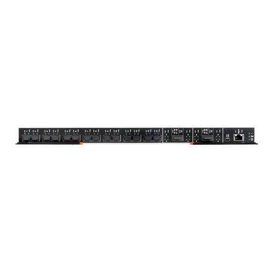
Chapter 1. The EN4093R 10 Gb Scalable Switch Introduction ® This User’s Guide provides information about the Lenovo Flex System™ Fabric EN4093R 10 Gb Scalable Switch (referred to as EN4093R or “switch” throughout this document). Figure 1. The EN4093R SFP+ module ports... - Page 10 The EN4093R provides flexible, reliable, and high-performance features that meet the demands of today's highly virtualized environments. The EN4093R provides pay-as-you-grow scalability. With optional licensing, you can easily and cost-effectively expand the number of available ports. Depending on the installed licenses, the scalable switch can provide up to sixty-four 10 Gigabit Ethernet (GbE) ports.
-
Page 11: Documentation
The console output described or referenced in this document might differ slightly from that displayed by your system. Output varies according to the type of Lenovo chassis and the firmware versions and options that are installed. Notices and Statements in this Document The caution and danger statements in this document are also in the multilingual Safety Information document, which is on the included Documentation CD. -
Page 12: The Documentation Cd
Command Reference for your specific switch and its installed firmware. See the documentation that came with your Lenovo chassis for information about the environmental conditions and specifications that are supported by the system. EN4093R 10 Gb Scalable Switch User’s Guide... -
Page 13: Chapter 2. Installing And Removing The En4093R
A Lenovo Flex System network adapter must be installed in each compute node with which you want to communicate. To enable the switch to communicate with a compute node, at least one switch must be installed in the Lenovo Flex System chassis. For details about network adapter installation, configuration, and use, see the documentation that comes with the Lenovo Flex System network adapter. - Page 14 Note: • I/O bays 1 and 2 support any standard Lenovo Flex System switch or pass-thru module. When you install an I/O network adapter in the left-most fabric connector on the compute node, these I/O bays support any switch with the same type of network interface that is used by the corresponding network adapter.
-
Page 15: Before Installing The En4093R
These labels also include the Media Access Control (MAC) address (on the uppermost handle) of the switch. Though helpful, the MAC address is not required for opening a service call. © Copyright 2015 Lenovo Chapter 2: Installing and Removing the EN4093R... -
Page 16: Installation Guidelines
• Blue on a component indicates touch points, where you can grip the component to remove it from or install it in the compute node or Lenovo Flex System chassis, open or close a latch, and so on. •... -
Page 17: System Reliability Guidelines
To help ensure proper cooling, performance, and system reliability, make sure that the following requirements are met: • Each of the bays on the rear of the Lenovo Flex System chassis contains either a module or a filler module. •... -
Page 18: Installing The En4093R
Installing the EN4093R Note: The following illustration shows how to install the switch in a Lenovo Flex System chassis. The appearance of your Lenovo Flex System chassis might be different; see the documentation for your Lenovo Flex System chassis for additional information. - Page 19 13. Make sure that the data (non-management) ports on the switch are enabled through the Chassis Management Module (CMM). © Copyright 2015 Lenovo Chapter 2: Installing and Removing the EN4093R...
-
Page 20: Removing Or Replacing The Switch
Removing or Replacing the Switch Note: The following illustration shows how to remove and replace the switch from the Lenovo Flex System chassis. The appearance of your Lenovo Flex System chassis might be different; see the documentation for your Lenovo Flex System chassis for additional information. -
Page 21: Connecting Switch Ports
Table 2. Pin out for the included mini-USB-to-RJ-45 cable PIN # Function Direction Not connected Not connected Not connected Not connected For additional information, see “Accessing the Switch Through the Serial-Port Interface” on page © Copyright 2015 Lenovo Chapter 2: Installing and Removing the EN4093R... -
Page 22: The Rj-45 Management Port
Disconnecting the Serial Console Cable To disconnect the serial console cable, grasp the connector and gently pull the cable from the switch. The RJ-45 Management Port Connecting RJ-45 Cables RJ-45 cables can be connected to the to external management port, and also to SFP+ ports that have legacy 1000BASE-T SFP transceiver modules. -
Page 23: Handling Transceiver Modules
Use minimal pressure when you insert the module into the switch port. Forcing the module into the port can cause damage to the module or port. • You can insert or remove the module while the Lenovo Flex System chassis is turned on. •... -
Page 24: Sfp+ Ports
2. If you have not already done so, touch the static-protective package that contains the SFP+ module to an unpainted metal surface of the Lenovo Flex System chassis or an unpainted metal surface on any other grounded rack component in the rack in which you are installing the switch for at least 2 seconds. - Page 25 1. Squeeze the release tabs and gently pull the fiber optic cable from the module. 2. Replace the protective caps on the ends of the fiber optic cable. © Copyright 2015 Lenovo Chapter 2: Installing and Removing the EN4093R...
-
Page 26: Qsfp+ Ports
Removing an SFP+ Module To remove the SFP+ module, complete the following steps. 1. Read the safety information that begins on page 5 “Installation Guidelines” on page 2. Read the information in “Handling Transceiver Modules” on page 3. Remove the fiber optic cable from the module that you want to replace. For more information about removing the cable, see “Disconnecting a Fiber Optic Cable”... - Page 27 1. Squeeze the release tabs and gently pull the fiber optic cable from the module. 2. Replace the protective caps on the ends of the fiber optic cable. © Copyright 2015 Lenovo Chapter 2: Installing and Removing the EN4093R...
-
Page 28: Locating The Information Panels, Leds, And External Ports
Removing a QSFP+ Module To remove the QSFP+ module from the switch port, complete the following steps. 1. Read the safety information that begins on page 5 “Installation Guidelines” on page 2. Read the information in “Handling Transceiver Modules” on page 3. - Page 29 Figure 4. The EN4093R front panel SFP+ module ports QSFP+ module ports RS-232 serial port (management only) RJ-45 External management port Switch status LEDs © Copyright 2015 Lenovo Chapter 2: Installing and Removing the EN4093R...
-
Page 30: Information Leds
Notes: • A yellow LED on the Lenovo Flex System chassis is lit when a system error or event has occurred. To identify the error or event, check the Lenovo Flex System management-module event log or the switch system log. -
Page 31: Switch Status Leds
When lit, this LED indicates a POST failure or critical alert. As a result, the system-error LED on the Lenovo Flex System chassis is also lit. When this LED is off and the green Power LED is lit, it indicates that the switch is working correctly. - Page 32 EN4093R 10 Gb Scalable Switch User’s Guide...
-
Page 33: Chapter 3. Configuring The En4093R
192.168.70.120, 192.168.70.121, 192.168.70.122, or 192.168.70.123 depending on the bay where the switch is installed. • If you change the IP address of the switch and restart the Lenovo Flex System chassis, the switch maintains this new IP address as its default value. •... - Page 34 “Related Documentation” on page Notes: • Unless otherwise stated, references to the CMM apply only to the Lenovo Flex System Chassis Management Module, which is the only type of management module that supports the switch. •...
-
Page 35: Establishing An Interface Through The Cmm
“Accessing the Switch Through the Browser-Based Interface” on page 38 additional information. If your system application requires that you use the SSHv2/Telnet client software, “Accessing the Switch Through the SSHv2/Telnet Interface” on page 37 additional information. © Copyright 2015 Lenovo Chapter 3: Configuring the EN4093R... -
Page 36: Enabling Management Through Data Ports
Enabling Management Through Data Ports To access and manage the switch through external interfaces, you must enable the data (non-management) ports and the ability to manage the switch through them. Use the information in the following table to configure your ports. Data Ports External Mgmt Description... -
Page 37: Accessing The Switch Through The Sshv2/Telnet Interface
For more information about configuring through the CLI, see the Application Guide and Command Reference for your specific switch and its installed firmware. © Copyright 2015 Lenovo Chapter 3: Configuring the EN4093R... -
Page 38: Accessing The Switch Through The Serial-Port Interface
Accessing the Switch Through the Serial-Port Interface The serial port provides basic communication RS-232 serial-data transfer through a terminal emulation program (such as Hyperterminal). Because messages from the power-on self-test (POST) and all initialization information are transmitted through the serial port, you can use the serial port to log in to the switch and access and configure the internal switching firmware. -
Page 39: Initial Configuration
After you log on to the switch, you must perform basic configuration tasks. For more information about configuring and managing the switch, see the Application Guide and Command Reference for your specific switch and its installed firmware. © Copyright 2015 Lenovo Chapter 3: Configuring the EN4093R... - Page 40 EN4093R 10 Gb Scalable Switch User’s Guide...
-
Page 41: Chapter 4. Updating The Firmware And Licensing
Determining the Level of Switch Firmware After you install the switch in the Lenovo Flex System chassis, make sure that the latest firmware is installed on the switch. To determine the level of the firmware that is installed, complete the following steps. -
Page 42: Obtaining The Latest Level Of Switch Firmware
Lenovo website into a directory on your file server. Then enable the file server and set its default directory to the directory where the switch firmware image resides. - Page 43 Where boot file is the file name of the boot image as it appears in the file server operating-system. 4. Reset and restart the switch as described in “Resetting and Restarting the Switch” on page © Copyright 2015 Lenovo Chapter 4: Updating the Firmware and Licensing...
-
Page 44: Resetting And Restarting The Switch
Resetting and Restarting the Switch To activate the new image or images, you must reset the switch. To reset the switch, complete the following steps: 1. Log on to the CMM CLI as described in the CMM documentation. If necessary, obtain the IP address of the CMM from your system administrator. -
Page 45: Acquiring Feature Licenses
Find help for the Features on Demand feature activation process • Provide feedback to Lenovo about the Features on Demand process Note: Your Lenovo ID and password are required to log into the Features on Demand website. © Copyright 2015 Lenovo... -
Page 46: Installing Feature Licenses
Installing Feature Licenses Once Features on Demand activation key files have been acquired, they must be installed on the switch. The example below illustrates use of the switch CLI, but other interfaces may also be used, such as the Browser Based Interface (BBI), or Simple Network Management Protocol (SNMP). -
Page 47: Chapter 5. Solving Problems
To ensure that it is fully operational, the switch processes a series of tests during power-up or a restart (Power-On Self-Test, or POST). These tests may take up to two minutes to complete. The Lenovo Flex System Chassis Management Module (CMM) reads the test results and displays them for you. During normal operation, these tests are completed without error, and the green switch Power LED is lit. - Page 48 The following table describes the basic critical and noncritical failures. This abbreviated list is representative; it is not an exhaustive list. An error code is associated with each failure. Error codes are displayed on the CMM Switch Information window. Be sure to note the applicable error code and corresponding failure.
-
Page 49: Appendix A. Getting Help And Technical Assistance
If you need help, service, or technical assistance or just want more information about Lenovo products, you will find a wide variety of sources available from Lenovo to assist you. This appendix will help you obtain additional information about Lenovo and Lenovo products, and determine what to do if you experience a problem with your Lenovo system or optional device. - Page 50 EN4093R 10 Gb Scalable Switch User’s Guide...
-
Page 51: Appendix B. Notices
Web sites. The materials at those Web sites are not part of the materials for this Lenovo product, and use of those Web sites is at your own risk. -
Page 52: Trademarks
(TBW). A device that has exceeded this limit might fail to respond to system-generated commands or might be incapable of being written to. Lenovo is not responsible for replacement of a device that has exceeded its maximum guaranteed number of program/erase cycles, as documented in the Official Published Specifications for the device. -
Page 53: Recycling Information
Lenovo makes no representations or warranties with respect to non-Lenovo products. Support (if any) for the non-Lenovo products is provided by the third party, not Lenovo. Some software might differ from its retail version (if available) and might not include user manuals or all program functionality. -
Page 54: Particulate Contamination
If Lenovo determines that the levels of particulates or gases in your environment have caused damage to the device, Lenovo may condition provision of repair or replacement of devices or parts on implementation of appropriate remedial measures to mitigate such environmental contamination. -
Page 55: Telecommunication Regulatory Statement
Properly shielded and grounded cables and connectors must be used in order to meet FCC emission limits. Lenovo is not responsible for any radio or television interference caused by using other than recommended cables and connectors or by unauthorized changes or modifications to this equipment. -
Page 56: European Union Emc Directive Conformance Statement
EU-Mitgliedsstaaten und hält die Grenzwerte der EN 55022 Klasse A ein. Um dieses sicherzustellen, sind die Geräte wie in den Handbüchern beschrieben zu installieren und zu betreiben. Des Weiteren dürfen auch nur von der Lenovo empfohlene Kabel angeschlossen werden. Lenovo übernimmt keine Verantwortung für die Einhaltung der Schutzanforderungen, wenn das Produkt ohne Zustimmung... -
Page 57: Vcci Class A Statement
Dieses Gerät ist berechtigt, in übereinstimmung mit dem Deutschen EMVG das EG-Konformitätszeichen - CE - zu führen. Verantwortlich für die Konformitätserklärung nach Paragraf 5 des EMVG ist die Lenovo (Deutschland) GmbH, Gropiusplatz 10, D-70563 Stuttgart. Informationen in Hinsicht EMVG Paragraf 4 Abs. (1) 4: Das Gerät erfüllt die Schutzanforderungen nach EN 55024 und EN 55022... -
Page 58: Japan Electronics And Information Technology Industries Association (Jeita) Statement
Japan Electronics and Information Technology Industries Association (JEITA) Statement Japanese Electronics and Information Technology Industries Association (JEITA) Confirmed Harmonics Guideline (products less than or equal to 20 A per phase). Japan Electronics and Information Technology Industries Association (JEITA) Confirmed Harmonics Guidelines with Modifications (products greater than 20 A per phase).
Need help?
Do you have a question about the Flex System Fabric EN4093R and is the answer not in the manual?
Questions and answers