Table of Contents
Advertisement
Quick Links
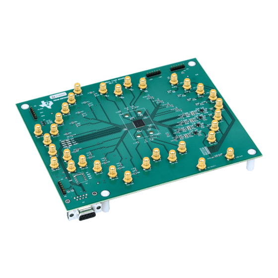
The Texas Instruments VCA8500BOARD evaluation module makes it easy to evaluate the performance of
the TI VCA8500 variable gain amplifier. This user's guide provides a description of the evaluation module
and its operation, schematic diagram, bill of materials, and the printed-circuit board layout.
....................................................................................................................
1
2
2.1
........................................................................................................................
3
3.1
3.2
3.3
3.4
4
5
5.1
5.2
5.3
6
6.1
6.2
6.3
7
7.1
7.2
7.3
1
2
Initial Start-up Screen
3
4
5
........................................................................................................................
6
7
Power Plane 1
8
.......................................................................................................................
9
10
1
Bill of Materials
Windows is a trademark of Microsoft Corporation.
SLOU216 - January 2008
Submit Documentation Feedback
..........................................................................................................
........................................................................................................
.........................................................................................................
.......................................................................................................
........................................................................................................
..........................................................................................................
................................................................................................................
.........................................................................................................
...........................................................................................
...................................................................................................
................................................................................................
..................................................................................
...............................................................................................
..............................................................................................
..........................................................................................
......................................................................................
....................................................................................................
..........................................................................................................
...........................................................................................................
.......................................................................................................
......................................................................................................
.......................................................................................................
....................................................................................................
................................................................................................................
................................................................................................................
...............................................................................................
.............................................................................................................
Contents
........................................................
List of Figures
List of Tables
User's Guide
SLOU216 - January 2008
VCA8500BOARD
VCA8500BOARD
2
2
2
2
2
2
2
3
3
3
3
4
4
4
4
4
7
7
7
11
13
3
4
5
6
7
8
8
9
10
11
11
1
Advertisement
Table of Contents

Subscribe to Our Youtube Channel
Related Manuals for Texas Instruments VCA8500BOARD


Summary of Contents for Texas Instruments VCA8500BOARD
-
Page 1: Table Of Contents
SLOU216 – January 2008 VCA8500BOARD The Texas Instruments VCA8500BOARD evaluation module makes it easy to evaluate the performance of the TI VCA8500 variable gain amplifier. This user's guide provides a description of the evaluation module and its operation, schematic diagram, bill of materials, and the printed-circuit board layout. -
Page 2: Description
The differential TGC outputs are buffered by operational amplifiers (OPA842) in a differential configuration with a differential gain of 1. When testing the VCA8500BOARD, outputs J21 through J28 (TGC outputs) must be terminated into 50-Ω loads such as those of a spectrum analyzer. This termination results in the proper matching for the output amplifiers, and no loss has to be taken into account. -
Page 3: Cw Outputs
19200 kbps. This baud rate is set internally on the microcontroller and is configured automatically in the PC software. Modes of Operation The three modes of operation for the VCA8500BOARD are Default Power Up, PC Control, and Direct-Control. Default-Power-Up Mode... -
Page 4: Pc Control Mode
VCA8500BOARD must be connected to the PC serial port. The program called VCA8500EVM then sets the proper baud rate for communication with the VCA8500BOARD. By using a PC to control the VCA8500, the entire device functionality is available for testing. The software provides the ability to select any of the clamp ranges and PGA gains settings, direct an input to any CW output, or power down the complete chip. -
Page 5: Main Program Window
VCA8500BOARD Full-Access Software If COM1 is used, then click the Click to continue box. Otherwise, select the correct COM port from the list that the program provided prior to selecting the continue box. Figure 3. Main Program Window The main program window allows the user to choose the mode of operation. -
Page 6: Cw Options Selection
VCA8500BOARD Full-Access Software When the VCA8500BOARD is controlled by the software, any input to the VCA8500 can be routed to any of the CW outputs via the CW Options selections. Each input channel is listed with a pull-down menu to select any of the ten available outputs (CW0 to CW9) or the Overflow option, which effectively disables the channel. -
Page 7: Other Program Functions
Printed-Circuit Board Layout, Bill of Materials, and Schematic The EVM software is available on the Texas Instruments Web site, ti.com, by looking in the VCA8500 product folder in the Tools and Software section. Other Program Functions Selecting the Exit command button exits the program. The Help pull-down menu contains information on the program and support information. -
Page 8: Ground
Printed-Circuit Board Layout, Bill of Materials, and Schematic Figure 6. Ground Figure 7. Power Plane 1 VCA8500BOARD SLOU216 – January 2008 Submit Documentation Feedback... -
Page 9: Power Plane
Printed-Circuit Board Layout, Bill of Materials, and Schematic Figure 8. Power Plane 2 SLOU216 – January 2008 VCA8500BOARD Submit Documentation Feedback... -
Page 10: Ground
Printed-Circuit Board Layout, Bill of Materials, and Schematic Figure 9. Ground VCA8500BOARD SLOU216 – January 2008 Submit Documentation Feedback... -
Page 11: Bill Of Materials
Capacitor, SMT, 0402 Capacitor, SMT, 0402,CER, 10pF, 50V, ±0.5pF, NPO Not Installed Panasonic ECJ-0EC1H470J C91, C105, C123, C131, Capacitor,SMT,0402 Capacitor, SMT, 0402, CER, 47pF, Not Installed C138, C154, C171, C178 50V, 5%, NPO SLOU216 – January 2008 VCA8500BOARD Submit Documentation Feedback... - Page 12 RES, SMT, 0402 Not Installed R47, R48, R75, R76, R101, R102 RES, SMT, 100 Ω, 1/16W, 1%, 100ppm Vishay/Dale CRCW04021000F100 R3, R4, R13, R14, R41, R42, RES, SMT, 0402 R69, R70, R97, R98 VCA8500BOARD SLOU216 – January 2008 Submit Documentation Feedback...
-
Page 13: Schematic
2) Line items 24 and 25 – W1 Short all three pads. Short W2 and W3. 3) Line item 20B – U19 Use OPA820 in place of the OPA642 Schematic The schematic drawings appear on the following page. SLOU216 – January 2008 VCA8500BOARD Submit Documentation Feedback... - Page 16 EVALUATION BOARD/KIT IMPORTANT NOTICE Texas Instruments (TI) provides the enclosed product(s) under the following conditions: This evaluation board/kit is intended for use for ENGINEERING DEVELOPMENT, DEMONSTRATION, OR EVALUATION PURPOSES ONLY and is not considered by TI to be a finished end-product fit for general consumer use. Persons handling the product(s) must have electronics training and observe good engineering practice standards.
- Page 17 IMPORTANT NOTICE Texas Instruments Incorporated and its subsidiaries (TI) reserve the right to make corrections, modifications, enhancements, improvements, and other changes to its products and services at any time and to discontinue any product or service without notice. Customers should obtain the latest relevant information before placing orders and should verify that such information is current and complete.
Need help?
Do you have a question about the VCA8500BOARD and is the answer not in the manual?
Questions and answers