Table of Contents
Advertisement
Trademarks
Autel
®
, MaxiSys
®
MaxiCheck
are trademarks of Autel Intelligent Technology Corp., Ltd.,
®
registered in China, the United States and other countries. All other marks
are trademarks or registered trademarks of their respective holders.
Copyright Information
No part of this manual may be reproduced, stored in a retrieval system or
transmitted, in any form or by any means, electronic, mechanical,
photocopying, recording, or otherwise without the prior written permission of
Autel.
Disclaimer of Warranties and Limitation of Liabilities
All information, specifications and illustrations in this manual are based on
the latest information available at the time of printing.
Autel reserves the right to make changes at any time without notice. While
information of this manual has been carefully checked for accuracy, no
guarantee is given for the completeness and correctness of the contents,
including but not limited to the product specifications, functions, and
illustrations.
Autel will not be liable for any direct, special, incidental, indirect damages or
any economic consequential damages (including the loss of profits).
IMPORTANT
Before operating or maintaining this unit, please read this manual carefully,
paying extra attention to the safety warnings and precautions.
For Services and Support
pro.autel.com
www.autel.com
1-855-288-3587/1-855-AUTELUS (North America)
0086-755-86147779 (China)
Support@autel.com
For technical assistance in all other markets, please contact your local
selling agent.
, MaxiDAS
®
, MaxiScan
®
, MaxiTPMS
i
®
, MaxiRecorder
®
, and
Advertisement
Table of Contents

Related Manuals for Autel MaxiSys MS906BT


Summary of Contents for Autel MaxiSys MS906BT
- Page 1 All information, specifications and illustrations in this manual are based on the latest information available at the time of printing. Autel reserves the right to make changes at any time without notice. While information of this manual has been carefully checked for accuracy, no...
- Page 2 Safety Information For your own safety and the safety of others, and to prevent damage to the device and vehicles upon which it is used, it is important that the safety instructions presented throughout this manual be read and understood by all persons operating or coming into contact with the device.
- Page 3 Safety Instructions The safety messages herein cover situations Autel is aware of. Autel cannot know, evaluate or advise you as to all of the possible hazards. You must be certain that any condition or service procedure encountered does not jeopardize your personal safety.
- Page 4 time. Any distraction may cause an accident. Refer to the service manual for the vehicle being serviced and adhere to all diagnostic procedures and precautions. Failure to do so may result in personal injury or damage to the test equipment. To avoid damaging the test equipment or generating false data, make ...
-
Page 5: Table Of Contents
CONTENTS USING THIS MANUAL...................1 ......................1 ONVENTIONS GENERAL INTRODUCTION.................3 DAS DS808 D .................3 ISPLAY ABLET ....................7 THER CCESSORIES GETTING STARTED....................9 ......................9 OWERING ....................13 OWERING DIAGNOSTICS......................14 ....................14 ETTING TARTED ..................15 EHICLE DENTIFICATION ......................21 AVIGATION ......................24 ....................... 25 IAGNOSIS ...................... - Page 6 ....................72 RINTING ETTING ....................74 IRMWARE PGRADE ....................74 OTIFICATION ENTER ......................75 PDATE ....................77 YSTEM ETTINGS ........................78 BOUT UPDATE......................... 79 10 SUPPORT......................81 ..................81 RODUCT EGISTRATION ..................82 UPPORT CREEN AYOUT ......................82 CCOUNT ....................83 OMPLAINT ......................86 OGGING ......................
-
Page 7: Using This Manual
Using This Manual This manual contains device usage instructions. Some illustrations shown in this manual may contain modules and optional equipment that are not included in your system. Contact your sales representative for availability of other modules and optional tools or accessories. - Page 8 IMPORTANT indicates a situation which, if not avoided, may result in damage to the test equipment or vehicle. Example: IMPORTANT Keep the cable away from heat, oil, sharp edges and moving parts. Replace damaged cables immediately. Hyperlink Hyperlinks, or links, that take you to other related articles, procedures, and illustrations are available in electronic documents.
-
Page 9: General Introduction
General Introduction Based on the Android operating system, MaxiDAS DS808 is featured with an extensive coverage of OE-level diagnostics. Installed with a fast quad-core processor, DS808 offers maximum convenience and efficiency for your diagnosis and analysis. The intuitive user interface makes using the device effortless through a 7-inch LCD touchscreen that displays at 1024 x 600 quality. - Page 10 is communicating/linking with the vehicle’s systems. The power LED displays different colors in response to the following scenarios: A. Green Illuminates green when the Display Tablet is charging and the battery level is above 90%. Illuminates green when the Display Tablet is powered on and the ...
- Page 11 Figure 2- 3 Display Tablet Top View Mini USB OTG Port Micro SD Card Slot – holds the micro SD card. 10. DB15-Pin Port – connects the main cable. 11. USB Port 12. Lock/Power Button – turns the device on & off with long press, or locks the screen with short press.
- Page 12 Technical Specifications Table 2- 1 Specifications Item Description Recommended Use Indoor Operating System Android 4.4.4 Processor Cortex-A9 processor (1.5 GHz) Memory 32GB 7-inch capacitive touchscreen with Display 1024x600 resolution Mini USB 2.0 USB 2.0 Connectivity Wi-Fi Micro SD card (supports up to 32GB) ...
-
Page 13: Other Accessories
237.8 mm (9.4”) x 148.6 mm (5.9”) x 35.5 mm Dimensions (W x H x D) (1.4”) Net Weight 788 g (1.74 lb.) ISO9141-2, ISO14230-2,ISO15765, K/L-Line, Flashing Code, SAE-J1850 VPW, SAE-J1850 Supported Automotive PWM, ISO11898(Highspeed, Middlespeed, Protocols Lowspeed and Singlewire CAN,fault-tolerant CAN), SAE J2610,GM UART,UART Echo Byte Protocol, Honda Diag-H Protocol, TP2.0, TP1.6 Other Accessories... - Page 14 User Manual Instructions on tool operations. Quick Guide Instructions on devices connection and diagnostic software update, etc.
-
Page 15: Getting Started
Getting Started Make sure the Display Tablet has sufficient power or is connected to the external power supply (see Power Sources on page 5). NOTE The images and illustrations depicted in this manual may differ slightly from the actual ones. Powering Up Long press the Lock/Power button on the top right of the Display Tablet to switch the unit on. - Page 16 NOTE The screen is locked by default when you turn on the display tablet. It is recommended to lock the screen to protect the information in the system and reduce the power consumption. Almost all operations on the Display Tablet are controlled through the touchscreen.
- Page 17 See on page 93 Quick Link for details. Provides quick search for the supported functions Function and vehicles of Autel diagnostic tools. See Function Viewer Viewer on page 94 for details. Locator and Navigation Buttons Operations of the Navigation buttons at the bottom of the screen are...
- Page 18 Button Name Description Back Returns to the previous screen. Android Returns to Android System’s Home screen. Home Displays a list of applications that are currently Recent Apps working. To open an App, tap it. To remove an app, swipe it to the top or bottom. Chrome Launches the Android built-in browser.
-
Page 19: Powering Down
Wi-Fi Enables/disables Wi-Fi when pressed. Airplane Enables/disables Airplane Mode when Mode pressed. Button Name Description Launches the Android System Settings System Settings screen when pressed. Powering Down All vehicle communications must be terminated before shutting down the Display Tablet. A warning message displays if you attempt to shut down the Display Tablet when it is communicating with the vehicle. -
Page 20: Diagnostics
Diagnostics By establishing a data link to the electronic control units of the vehicle being serviced directly, the Diagnostics application allows you to retrieve ECU information, read & erase DTCs, view live data, and perform active tests. The Diagnostics application can access the electronic control unit (ECU) for various vehicle control systems, such as engine, transmission, antilock brake system (ABS), airbag system (SRS) and more. -
Page 21: Vehicle Identification
Vehicle Manufacturer Buttons Top Toolbar Buttons The operations of the toolbar buttons at the top of the screen are listed and described in the table below: Table 4- 1 Top Toolbar Buttons Button Name Description Home Returns to the MaxiDAS Job Menu. Provides a fast way to identify the test vehicle. - Page 22 Auto VIN Scan Manual VIN Input Automatic Selection Manual Selection Auto VIN Scan The MaxiDAS diagnostic system features the latest VIN-based Auto VIN Scan function to identify vehicles in just one touch, which allows the technician to quickly detect vehicles, scan all the diagnosable ECUs on every vehicle and run diagnostics on the selected system.
- Page 23 Table 4- 3 Sample Auto Detect Screen Review the information to make sure it is correct. Tap OK to confirm the vehicle profile or NO if the information is not correct. Figure 4- 4 Sample Vehicle Profile Screen The tool would start establishing vehicle communication and reading control unit information.
- Page 24 Figure 4- 5 Sample Diagnostic Screen Manual VIN Input For some vehicles that do not support the Auto VIN Scan function, the MaxiDAS diagnostic system allows you to enter the vehicle VIN manually. To perform Manual VIN Input Tap the Diagnostics application button from the MaxiDAS Job Menu.
- Page 25 Figure 4- 6 Sample Manual VIN Input Screen Tap Done. The vehicle will be identified in a few seconds. Once the matching is successful, the system will guide you to the Vehicle Diagnostics screen directly. Tap Cancel to exit Manual Input. Automatic Selection In some cases when users have selected the vehicle brand instead of performing Auto VIN Scan in the first place, the system still provides an...
- Page 26 To perform Automatic Selection Tap the Diagnostics application button from the MaxiDAS Job Menu. The Vehicle Menu displays. Tap the vehicle brand of the test vehicle. Tap Automatic Selection and the system will proceed to acquire VIN information automatically. Follow the on-screen instruction to go into diagnostic screen.
-
Page 27: Navigation
Navigation This section describes how to operate the Diagnostics screen and select test options. Diagnostics Screen Layout Figure 4- 8 Sample Diagnostics Screen The diagnostic screens typically include four sections. Diagnostics Toolbar Status Information Bar Main Section Functional Buttons Diagnostics Toolbar The Diagnostics Toolbar contains a number of buttons that allow you to print or save the displayed data and make other controls. - Page 28 Table 4- 2 Diagnostics Toolbar Buttons Button Name Description Home Returns to the MaxiDAS Job Menu. Exits the diagnostic session of the currently Vehicle identified test vehicle and returns to the vehicle Swap menu screen. Opens the settings screen. See Settings on page Settings...
- Page 29 Tap the Diagnostics application button from the MaxiDAS Job Menu. The Data Logging button on the diagnostic toolbar is available throughout the whole Diagnostics operations. Tap the Data Logging button. The button displays blue during the active recording process. Tap the Data Logging button again to end recording. A submission form will display to let you fill in the report information.
-
Page 30: Main Menu
Confirmation Messages Confirmation messages usually display as an “Information” screen, which inform you when you are about to perform an action that cannot be reversed or when an action has been initiated and your confirmation is needed to continue. When a user-response is not required to continue, the message displays briefly before automatically disappearing. -
Page 31: Diagnosis
Figure 4- 9 Sample Main Menu Diagnosis – a comprehensive section which includes all available functions: reading, clearing, saving and printing diagnostic information, as well as performing active tests and special functions. Hot Function – a separate section designed to perform vehicle scheduled service and maintenance, such as to reset the service lights and perform calibration for various systems. - Page 32 Auto Scan The Auto Scan function performs a comprehensive scanning over all the ECUs in the vehicle’s systems in order to locate and retrieve DTCs. The Figure 4- 10 Sample Auto Scan Operation Screen sample operation screen of Auto Scan displays as below: Navigation Bar Main Section Functional Buttons...
- Page 33 the Display Tablet cannot accurately locate it. Fault(s) | #: Fault(s) indicates there is/are detected fault code(s) present; “#” indicates the number of the detected faults. Pass | No Fault: Indicates the system has passed the scanning process and no fault has been detected. Column 4 –...
- Page 34 Control Units This option allows you to manually locate a required control system for testing through a series of choices. Please follow the menu driven procedures and make proper selection each time. The program will guide you to the diagnostic function menu after a few choices you’ve made. Figure 4- 11 Sample Function Menu The Function Menu options vary slightly for different vehicles.
- Page 35 NOTE With the diagnostic toolbar on top of the screen throughout the whole diagnostic procedures, you are allowed to make various controls of the diagnostic information at any time, such as printing and saving the displayed data, getting help information, or performing data logging, etc. ...
- Page 36 Functional Button – in this case, only an ESC (or sometimes a Back) button is available; tap it to exit after viewing. Read Codes This function retrieves and displays the DTCs from the vehicle’s control system. The Read Codes screen varies for each vehicle being tested. On some vehicles, freeze frame data can also be retrieved for viewing.
- Page 37 etc. Freeze frame – tap this to view the freeze frame. Search – tap this icon to search the fault code related information in Google. ESC – tap it to return to the previous screen or exit the function. ...
- Page 38 Figure 4- 14 Sample Live Data Screen Diagnostics Toolbar Buttons – tap the drop-down button at the top center of the screen and the toolbar buttons will display. See Table 4- 2 Diagnostics Toolbar Buttons on page 22 for detailed descriptions of the operations for each button.
- Page 39 mode, and one Help button on the right that you can tap for additional information. Each parameter item displays the selected mode independently. Analog Gauge Mode – displays the parameters in form of an analog meter graph. Text Mode – this is the default mode which displays the parameters in texts and shows in list format.
- Page 40 comparison. There are three control buttons available on the top right side of the screen under this mode. To edit the waveform color and line thickness in a data graph Select 1 to 3 parameter items to display in Waveform Graph mode.
- Page 41 NOTE This mode supports Graph Merge for 2 to 3 parameter items only, so select no less than 2 and no more than 3 items each time when making graph merge. To cancel Graph Merge mode, tap the drop-down button on the right side of the parameter name and select a data display mode.
- Page 42 Buzzer Alarm – switches the alarm on and off. The alarm function makes a beep sound as a reminder whenever the data reading reaches the preset minimum or maximum point. To set threshold limits for the parameter values Tap the Setting functional button at the bottom of the Live Data screen.
- Page 43 before the data recording start point for reference (for Auto trigger mode only). To perform setting for live data record Tap the Setting functional button at the bottom of the Live Data screen. Tap the Record navigation button. > button on the right of Trigger Type bar and select the Tap the ○...
- Page 44 Figure 4- 16 Sample Active Test Screen The functional buttons at the lower right corner of the Active Test screen manipulate the test signals. The operational instructions are displayed on the main section of the test screen. Simply follow the on-screen instructions and make appropriate selections to complete the tests.
-
Page 45: Hot Functions
Figure 4- 17 Sample Special Functions Screen Hot Functions The Service section is specially designed to provide you with quick access to the vehicle systems for various scheduled service and maintenance performances. The typical service operation screen is a series of menu driven executive commands. - Page 46 time the oil is changed, so the system can calculate when the next oil change is required. Tire Pressure Monitor System (TPMS) Service This function allows you to quickly look up the tire sensor IDs from the vehicle’s ECU, as well as to perform TPMS programming and reset procedures after tire sensors are replaced.
-
Page 47: Generic Obd Ii Operations
complete a DPF regeneration cycle, you will notice that the DPF light will automatically turn off. Generic OBD II Operations A fast-access option for OBD II/EOBD vehicle diagnosis is available on the Vehicle Menu screen. This option presents a quick way to check for DTCs, isolate the cause of an illuminated malfunction indicator lamp (MIL), check monitor status prior to emissions certification testing, verify repairs, and perform a number of other services that are emissions-related. - Page 48 Select a specific protocol under the Protocol option. Wait for the Figure 4- 18 Sample OBD II Diagnostic Menu OBD II Diagnostic Menu to appear. NOTE Tapping the i button displayed beside the function name opens a bubble ○ with additional function information. Select a function option to continue.
- Page 49 DTC & FFD When this function is selected, the screen displays a list of Stored Codes and Pending Codes. When the Freeze Frame data of certain DTCs are available for viewing, a snowflake button will display on the right side of the DTC item.
- Page 50 to 80 warm-up cycles, the fault is automatically cleared from memory. Test results reported by this service do not necessarily indicate a faulty component or system. If test results indicate another failure after additional driving, then a DTC is set to indicate a faulty component or system and the MIL is illuminated.
-
Page 51: Exiting Diagnostics
Live data can be displayed in various modes, see Live Data on page 31 for detailed information. O2 Sensor Monitor This option allows retrieval and viewing of O2 sensor monitor test results for the most recently performed tests from the vehicle’s on-board computer. The O2 Sensor Monitor test function is not supported by vehicles which communicate using a controller area network (CAN). - Page 52 stop all communications with the vehicle before closing the Diagnostics application. NOTE Damage to the vehicle electronic control module (ECM) may occur if communication is disrupted. Make sure all connections, such as USB cable and wireless connection, are properly connected at all times during testing. Exit all tests before disconnecting the test connection or powering down the tool.
-
Page 53: Maxifix
MaxiFix The MaxiFix application launches the on-line troubleshooter database, which not only provides you virtually all common diagnostic trouble codes (DTCs) database for most vehicles, but also serves as a forum allowing you to network with other MaxiDAS users, and gives you access to a vast database of repair and diagnostic tips along with proven filed fixes. - Page 54 The MaxiFix screen layout consists of 3 main areas: The Header – the tool bar across the top of the screen which allows you to select vehicles and perform searches. The Main Screen – located at the center of the screen displaying content based on the vehicle attributes and keywords specified.
- Page 55 Select the make of the vehicle from the list. Select the model of the vehicle from the list. Select the submodel of the vehicle from the list. Select the engine of the vehicle from the list. After completing the vehicle selection procedure, the identified vehicle is shown on the Header.
-
Page 56: Operations
Proven Results! The powerful MaxiFix database gives you proven results! The typical MaxiFix Tips combine actual workshop fixes and data which may include: OBD II Fault Codes description and reference – helps in diagnostic assessment by making clear the nature of an automotive problem that... - Page 57 community, and allows you to view your personal profile, select your vehicle preference, and share your tips. My Messages – shows a list of message notifications which is relevant to your activities in the Question section. Support – opens the FAQ page, or a message box for contacting ...
- Page 58 Ask, the third option on the Navigation Menu at the bottom of the screen, allows you to ask a question about a particular vehicle repair issue in the community. To ask a MaxiFix Question If not already done, click Select Vehicle on the Header to specify the vehicle you are asking about.
- Page 59 Marked Posts – opens a list with links to Tips and discussions that you are actively participating in. My Profile – allows you to view your Autel account information including: your Autel ID, personal information, MaxiFix score, phone number and register time, and edit your portrait.
- Page 60 Use the Cancel button at the right-side bottom of the page to cancel your tip and return to the My MaxiFix page. Or use the Submit button at the right-side bottom of the page to contribute your tip to the community. Use the Attach File button at the left-side bottom of the page to include images or other supporting data with your question.
- Page 61 Select “Adopted Answers” Members are requested to select one Adopted Answer from all of the responses on My Messages page before closing a question. The community members who provided the Adopted Answer are rewarded with scores for their contribution. About Adopted Answer: Only one answer can be selected as “Adopted Answer”.
- Page 62 Support Support, the last option on the Navigation Menu at the bottom of the screen, opens a page that provides 2 ways to gain support from MaxiFix: A message form to contact the administrator of MaxiFix. A Frequently Asked Questions (FAQ) link that answers the most frequent questions we hear from MaxiFix community members.
-
Page 63: Shop Manager
Shop Manager The Shop Manager application helps you to manage the workshop information, customer information records, and keep test vehicle history records, which can be a great assist in dealing with daily workshop business and improves customer service. There are three main functions available: Vehicle History ... -
Page 64: Vehicle History
Button Name Description Create a new customer account file. Account Opens a note form, which allows you to create History audio record, attach picture or video, or edit text Notes notes, etc. Opens the Vehicle History screen which displays Vehicle History the correlated test vehicle records. - Page 65 Tap the Shop Manager application on the MaxiDAS Job Menu. Select Vehicle History. Tap the Diagnostics button at the bottom of the thumbnail of a vehicle record item. Or select a vehicle record item by tapping the thumbnail. A Historical Test record sheet displays. Check the recorded information of the recorded test vehicle and tap the Diagnostics button on the upper right corner.
-
Page 66: Workshop Information
Select the specific vehicle history record thumbnail from the main section. The Historical Test record sheet displays. Tap the Edit button to start editing. Tap on each item to input the corresponding information or add attaching files or images. NOTE The vehicle VIN number or license and the customer information account are correlated by default. -
Page 67: Customer Manager
To edit the Workshop Information sheet Tap the Shop Manager application on the MaxiDAS Job Menu. Select Workshop Information. Tap the Edit button on the top toolbar. Tap on each field to input the appropriate information. Tap Done to save the updated workshop information sheet, or tap Cancel to exit without saving. - Page 68 Tap the Edit button on the top toolbar to start editing. Tap on the input field where needs to be altered or supplemented and enter updated information. Tap Done to save the updated information or tap Cancel to exit without saving. ...
- Page 69 Figure 6- 4 Sample History Notes Screen Functional Buttons – navigates and make various controls of the function. Main Section – displays the note list on the left column and the detail information of the selected note on the right column. Table 6- 2 Function Buttons in History Notes Button Name...
- Page 70 Button Name Description Opens the image file for selection and adds the selected photos to History Photos Notes. Save Saves notes. To add a note in History Notes Access History Notes. Tap the Add Notes button. An edit window displays. Tap on the Title bar to input a note title.
-
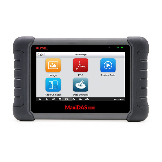
Page 71: Data Manager
Data Manager The Data Manager application is used to store, print, and review the saved files. Most operations are controlled through the toolbar. Selecting the Data Manager application opens the file system menu. Different file types are sorted separately under different options, there are Figure 7- 1 Sample Data Manager Main Screen five types of information files to be viewed or played back. - Page 72 Figure 7- 2 Sample Image Screen Toolbar Buttons – used to edit, print and delete the image files. See the following table for detailed information. Main Section – displays the stored images. Table 7- 1 Toolbar Buttons in Image Button Name Description Back...
- Page 73 > Support & Updates > Firmware & Downloads > UPDATE CLIENT and install to your PC. The Maxi PC Suite consists of Autel Printer, MaxiSys Pinter and PC Suite. Double click on Setup.exe item. Select the installation language and the printer driver installation wizard will load momentarily.
- Page 74 Select the images that need to be deleted by tapping the thumbnail images, the selected thumbnail displays a tick icon at the bottom right corner. Tap the Delete button and then tap Delete Selected. The selected images will be deleted. PDF Files The PDF section stores and displays all PDF files of saved data.
- Page 75 Drop-down Toolbar – tap the button at the top center of the screen to open the Drop-down Toolbar. Main Section – displays the recorded data frames. Navigation Toolbar – allows you to manipulate data playback. Use the Navigation Toolbar buttons to playback the record data from frame to frame.
-
Page 76: Settings
Settings Selecting Settings application opens a setup screen, on which you can adjust default setting and view information about the MaxiDAS system. There are eight options available for the MaxiDAS system settings: Unit Language Printing Setting Firmware Upgrade ... -
Page 77: Language
Figure 8- 1 Sample Unit Setting Screen Language This option allows you to adjust the display language for the MaxiDAS system. To adjust the language setting Tap the Settings application on the MaxiDAS Job Menu. Tap the Language option on the left column. Figure 8- 2 Sample Language Setting Screen Select the required language. -
Page 78: Printing Setting
MaxiDAS Job Menu. Or select another setting option for system setup. Printing Setting This option allows you to print any data or information anywhere and anytime via Wi-Fi connection. To setup the printer connection Tap the Settings application on the MaxiDAS Job Menu. Tap the Printing Setting option on the left column. - Page 79 Display Tablet. Follow the instructions below to realize this function. To install the printer driver program to a computer Download the Maxi PC Suite from www.autel.com and install to your PC. Double click on Setup.exe item. Select the installation language and the wizard will load momentarily.
-
Page 80: Firmware Upgrade
Internet. It is highly recommended to keep this function on all the time, so you won’t miss out any new update for MaxiDAS or event from Autel. Internet access is required for receiving on-line messages. -
Page 81: Auto Update
Tap the Settings application on the MaxiDAS Job Menu. Tap the Notification Center option on the left column. Tap the ON/OFF button to enable or disable the Notifications function. If the function is enabled the button turns blue, or if disabled the button turns gray. - Page 82 To set auto system or vehicle update Tap the Settings application on the MaxiDAS Job Menu. Tap the Auto Update option on the left column. The three auto Figure 8- 6 Sample Auto Update Screen update items list on the right. Switch the ON the button on the right of item that you want to auto update.
-
Page 83: System Settings
Done to complete the time setting. NOTE Internet connection is necessary for auto update, otherwise it would not work even if you have already switch it on. Make sure the tool is connected to the Internet for the time you have set. System Settings This option provides you a direct access to the Android background system setting screen, on which you can adjust various system settings for the... -
Page 84: About
Tapping a specific app shortcut button enables you to switch directly to the selected application screen. Long pressing a specific app shortcut button displays the app menu, on which you can select and change the app shortcut. Pressing and dragging the App Switcher icon around allows you to ... -
Page 85: Update
Update The Update application allows you to download the latest released software. The updates can improve the MaxiDAS applications’ capabilities, typically by adding new tests, new models, or enhanced applications to the database. The Display Tablet automatically searches for available updates for all of the MaxiDAS software when it is connected to the internet. - Page 86 Left Side – displays the MaxiDAS device model information and serial number. Right Side – displays an update progress bar indicating the completion status. Main Section Left Column – displays vehicle logos and update software version information. Middle Column –...
-
Page 87: Support
On the Sign In page, input your account ID and other information to log in, if you already have an account. If you are a new member to Autel and do not have an account yet, click the Create Autel ID button on the left side. -
Page 88: Support Screen Layout
Support Screen Layout The Support application screen is navigated by 4 simple buttons on the top navigation bar, operation of each is described below in turn from left to right: Home Button – returns to the MaxiDAS Job Menu. Back –... -
Page 89: User Complaint
User Info – displays detailed information of your registered on-line Autel account, such as your Autel ID, Name, Address and other contact information, etc. Device Info – displays the registered product information, including the Serial Number, Registration Date, Expire Date, and Warranty Period. - Page 90 The User Complaint screen consists of two parts. Option Bar Period Filter – displays only the complaint records within the defined period on the list. Status Filter – displays the corresponding complaint records according to the selected case status. New Complaint Button –...
- Page 91 Select the required processing time on the last section according to the urgency of the case. Tap Submit to send the completed form to Autel’s online service center, or tap Reset to refill it. The submitted complaints will be carefully read and handled by the service personnel, and the respond speed may depend on the processing time you’ve required.
-
Page 92: Data Logging
Data Logging The Data Logging section keeps records of all sent or unsent (saved) data loggings on the diagnostic system. The support personnel receive and process the submitted reports through the Support platform, and send back problem solutions within 48 hours to the corresponding Data Logging session, on which you are also allowed to have a direct conversation with Figure 10- 3 Sample Data Logging Screen the support personnel. -
Page 93: Communities
The Communities section launches and synchronizes with the Technical Forums on Autel’s official website www.autel.com, where you are allowed to discuss technical topics or share information with, as well as ask for technical advices or offer technical supports to all other members in Autel’s online support communities. ... -
Page 94: User Profile
pinpoint the topics you are most interested with. > Tap the ○ button on the right side of the topic item to view the discussion. The posts contents are displayed. Browse through all the posts by sliding the screen up and down. Tap Go to original post when reaching the end of the discussion to return to the first post. -
Page 95: Training Channels
list. Training Channels The Training section provides quick links to Autel’s online video accounts. Select a video channel by the language to see all the available online tutorial videos from Autel for various technical supports, such as product usage techniques and vehicle diagnostics practice, etc., may be available for your interests. -
Page 96: Academy
Academy Autel provides various tutorial articles and technical bulletins produced by top-notch technicians and product experts. Please view the materials that are saved on the Display Tablet or view more technical articles from our online forum by clicking the links displayed under this application. -
Page 97: Remote Desk
The Remote Desk application launches the TeamViewer Quick Support program, which is a simple, fast and secure remote control screen. You can use the application to receive ad-hoc remote support from Autel’s support center, colleagues, or friends, by allowing them to control your MaxiDAS tablet on their PC via the TeamViewer software. - Page 98 TeamViewer screen displays and the device ID is generated and shown. Your partner must install the Remote Control software to his/her computer by downloading the TeamViewer full version program online (http://www.teamviewer.com), and then start the software on his/her computer at the same time, in order to provide support and take control of the Display Tablet remotely.
-
Page 99: Quick Link
Quick Link The Quick Link application provides you with convenient access to Autel’s official website and many other well-known sites in automotive service, which offer you abundant information and resources, such as technical help, knowledge base, forums, training, and expertise consultations, etc. -
Page 100: Function Viewer
Function Viewer The Function Viewer allows you to search the functions supported by our tools and the version information. There are two ways of searching, either by searching the tool and the vehicle or searching the functions. To search by the vehicle Tap the Function Viewer application on the MaxiDAS Job Menu. - Page 101 Figure 14- 2 Sample Function Viewer Screen 2 To search by the functions Tap the Function Viewer application on the MaxiDAS Job Menu. The Function Viewer application screen displays. Tap the tool name on the top left to drop down the tool list, tap the one you want to search.
- Page 102 Figure 14- 3 Sample Function Viewer Screen 3...
-
Page 103: Maintenance And Service
Maintenance and Service Maintenance Instructions The following shows how to maintain your devices, together with precautions to take. Use a soft cloth and alcohol or a mild window cleaner to clean the touch screen of the tablet. Do not use any abrasive cleansers, detergent, or automotive chemicals ... -
Page 104: Troubleshooting Checklist
Your device may have not been connected to the charger properly. Check the connector. NOTE If your problems persist, please contact Autel’s technical support personnel or your local selling agent. About Battery Usage Your tablet is powered by a built-in Lithium-ion Polymer battery. This means that, unlike other forms of battery technology, you can recharge your battery while some charge remains without reducing your tablet’s autonomy due to... -
Page 105: Service Procedures
DANGER The built-in Lithium-ion Polymer battery is factory replaceable only; incorrect replacement or tampering with the battery pack may cause an explosion. Do not use a damaged battery charger. Do not disassemble or open crush, bend or deform, puncture or shred. ... - Page 106 Email: support@autel.com Address: 6th-10th floor, Building B1, Zhiyuan, Xueyuan Road, Xili, Nanshan, Shenzhen, 518055, China AUTEL NORTH AMERICA Phone: 855-AUTEL-US (855-288-3587) Monday-Friday 9am-6pm EST Website: www.autel.com Email: ussupport@autel.com Address: Suite 200, 175 Central Avenue, Farmingdale, New York, USA.
- Page 107 8th Floor, Building B1, Zhiyuan, Xueyuan Road, Xili, Nanshan, Shenzhen, 518055, China Other Services You can purchase the optional accessories directly from Autel’s authorized tool suppliers, and/or your local distributor or agent. Your purchase order should include the following information: Contact information ...
-
Page 108: Compliance Information
Compliance Information FCC Compliance FCC ID: WQ8-1610MX808 This device complies with Part 15 of the FCC rules and Industry Canada’s license-exempt RSSs. Operation is subject to the following two conditions: This device may not cause harmful interference. This device must accept any interference received, including interference that may cause undesired operation. - Page 109 -- Reorient or relocate the receiving antenna. -- Increase the separation between the equipment and receiver. -- Connect the equipment into an outlet on a circuit different from that to which the receiver is connected. -- Consult the dealer or an experienced radio/TV technician for help. Changes or modifications not expressly approved by the party responsible for compliance could void the user’s authority to operate the equipment.
- Page 110 CE COMPLIANCE This product is declared to conform to the essential requirements of the following Directives and carries the CE mark accordingly: EMC Directive 2014/30/EU R&TTE Directive 1999/5/EC Low Voltage Directive 2014/35/EU...
-
Page 111: Warranty
Warranty Limited One Year Warranty Autel Intelligent Technology Corp., Ltd. (the Company) warrants to the original retail purchaser of this MaxiDAS Diagnostic Device, that should this product or any part thereof during normal consumer usage and conditions, be proven defective in material or workmanship that results in product... - Page 112 IMPORTANT All contents of the product may be deleted during the process of repair. You should create a back-up copy of any contents of your product before delivering the product for warranty service.
Need help?
Do you have a question about the MaxiSys MS906BT and is the answer not in the manual?
Questions and answers