Table of Contents
Advertisement
Quick Links
Advertisement
Table of Contents

Related Manuals for Autel MaxiSys Ultra ADAS


Summary of Contents for Autel MaxiSys Ultra ADAS
- Page 1 MaxiSys Ultra ADAS...
- Page 2 Autel will not be liable for any direct, special, incidental, or indirect damages, or for any economic consequential damages (including the loss of profits) as a result of using this product.
- Page 3 The safety messages herein cover situations Autel is aware of at the time of publication. Autel cannot know, evaluate or advise you as to all of the possible hazards. You must be certain that any condition or service procedure encountered does not jeopardize your...
- Page 4 DANGER When an engine is operating, keep the service area WELL VENTILATED or attach a building exhaust removal system to the engine exhaust system. Engines produce carbon monoxide, an odorless, poisonous gas that causes slower reaction time and can lead to serious personal injury or loss of life.
-
Page 5: Table Of Contents
CONTENTS 1 USING THIS MANUAL ....................1 ..................... 1 ONVENTIONS 1.1.1 Bold Text ...................... 1 1.1.2 Notes and Important Messages ..............1 1.1.3 Hyperlink ....................... 1 1.1.4 Illustrations ....................1 1.1.5 Procedures ....................2 2 GENERAL INTRODUCTION ..................3 ....................3 ABLET 2.1.1 Function Description .................. - Page 6 3.1.2 Locator and Navigation Buttons ..............16 3.1.3 System Status Icons ................... 17 ....................18 OWER 3.2.1 Reboot System ................... 18 4 DIAGNOSTICS ......................19 .......... 19 STABLISH EHICLE OMMUNICATION AND ELECTION 4.1.1 Establish Vehicle Communication .............. 19 ..................... 24 ETTING TARTED 4.2.1...
- Page 7 4.8.2 Function Descriptions ................. 52 ..................55 IAGNOSTIC EPORT 4.9.1 Pre-Scan and Post-Scan Functions ............55 4.9.2 Diagnostics Report Saving, Viewing, and Sharing ........56 4.10 ..................... 59 IAGNOSTICS 5 WHEEL ALIGNMENT ....................61 ..................61 REPARATORY ..................61 RECAUTIONS IN ............
- Page 8 6 ADAS CALIBRATION ....................120 ..................120 REPARATORY ............120 EHICLE OMMUNICATION AND ELECTION 6.2.1 Specific ADAS Calibration Function............121 ADAS C ..............122 ALIBRATION ROCEDURES 6.3.1 Select a Situation That Needs Calibration ..........122 6.3.2 Required Calibration Tools ............... 123 6.3.3 Calibration Preparations ................
- Page 9 ....................138 EVIEW ....................138 OGGING ....................139 NINSTALL 9 BATTERY TEST ......................140 BAS BT506 B ..............141 ATTERY ESTER 9.1.1 Function Description ................. 141 9.1.2 Power Sources ..................142 9.1.3 Technical Specifications ................142 ..................143 REPARATION 9.2.1 Inspect the Battery ..................
- Page 10 10.7 ADAS & A ................155 LIGNER ETTINGS 10.7.1 Common Settings ..................156 10.7.2 Calibration Frame Connection ..............159 10.7.3 Network Configuration ................160 10.7.4 Update ...................... 162 10.7.5 Maintenance & Service ................162 10.7.6 Wheel Alignment Software Settings............191 10.8 ....................
- Page 11 16 MAXIVIDEO ........................ 215 17 QUICK LINK ....................... 216 18 REMOTE DESKTOP ....................217 18.1 ....................217 PERATIONS 19 USER FEEDBACK ..................... 219 20 AUTEL USER CENTER ..................... 220 21 MAINTENANCE AND SERVICE ................222 21.1 ................222 AINTENANCE NSTRUCTIONS 21.2 .................
-
Page 12: Using This Manual
Using This Manual This manual contains device usage instructions. Some illustrations shown in this manual may contain modules and optional equipment that are not included in your system. 1.1 Conventions The following conventions are used: 1.1.1 Bold Text Bold text is used to highlight selectable items such as buttons and menu options. Example: Tap OK. -
Page 13: Procedures
vehicle being tested. Observe the menu titles and on-screen instructions to make correct option selection. 1.1.5 Procedures An arrow icon indicates a procedure. Example: ➢ To power down the MaxiSys tablet Long press (press and hold) the Power/Lock button. Tap the Power Off option. Tap OK. -
Page 14: General Introduction
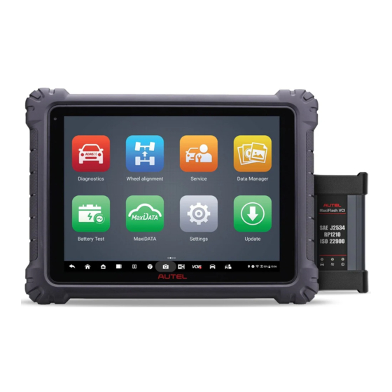
General Introduction There are two main components to the MaxiSys system: MaxiSys Tablet — the central processor and monitor for the system. ⚫ MaxiFlash VCI — the vehicle communication interface. ⚫ This manual describes the construction and operation of these devices and how they work together to deliver diagnostic solutions. - Page 15 Table 2-1 Power LED Description Color Description Lights green when the tablet is charging and the ⚫ battery level is above 90%. Green Lights green when the tablet is powered on and the ⚫ battery level is above 15%. Lights yellow when the tablet is charging and the battery Yellow Power level is below 90%.
-
Page 16: Docking Station
Figure 2-3 MaxiSys Tablet Top View 11. Mini USB Port — cannot be used with the USB Port simultaneously 12. USB Port 13. USB Port 14. Mini SD Card Slot 15. HDMI (High-Definition Multimedia Interface) Port 16. Head Phone Jack 17. -
Page 17: Power Sources
The indicator light displays differently in response to the tablet status described below: A. Green light — battery power of the tablet is sufficient (≥90%) B. Yellow light — battery level is above 14% but below 90% C. Red light — battery level is below 14% NOTE Ensure the docking station is clear of any small metal or other conductive parts to avoid short circuit damage to the charger and the tablet. -
Page 18: Technical Specifications
2.1.4 Technical Specifications Table 2-2 Tablet Specifications Item Description Operating System Android 7.0 Processor Octa-core processor (4 x 2.3 GHz; 4 x 1.7 GHz) Memory 4 GB RAM & 256 GB on-board memory 12.7-inch TFT-LCD with 2732 x 2048 resolution & Display capacitive touchscreen ⚫... -
Page 19: Maxiflash Vci
Item Description Weight 2.18 kg (4.81 lbs.) PLC J2497, ISO-15765, SAE-J1939, ISO-14229 UDS, SAE-J2411 Single Wire Can (GMLAN), ISO-11898-2, ISO-11898-3, SAE-J2819 (TP20), TP16, ISO-9141, ISO- 14230, SAE-J2610 (Chrysler SCI), UART Echo Byte, Protocols SAE-J2809 (Honda Diag-H), SAE-J2740 (GM ALDL), SAE-J1567 (CCD BUS), Ford UBP, Nissan DDL UART with Clock, BMW DS2, BMW DS1, SAE J2819 (VAG KW81), KW82, SAE J1708, SAE-J1850 PWM (Ford SCP), SAE-J1850 VPW (GM Class2), ISO 13400, CAN FD... - Page 20 DC Power Supply Input Port Vehicle Data Connector Ethernet Port Vehicle LED Flashes green when the device is communicating with the vehicle system ⚫ Connection LED Lights solid green when the device is properly connected with the tablet via the ⚫...
-
Page 21: Power Sources
2.2.2 Power Sources The VCI device can receive power from the following sources: Vehicle Power ⚫ AC/DC Power Supply ⚫ 2.2.2.1 Vehicle Power The VCI device operates on 12/24 volts vehicle power, which receives power via the vehicle data connection port. The device powers on whenever it is connected to an OBDII/EOBD compliant Data Link Connector (DLC). -
Page 22: Accessories Kit
2.3 Accessories Kit 2.3.1 Main Cable The VCI device can be powered through the Autel main cable V2.0 (the V2.0 icon can be seen on the cable) when connected to an OBDII/EOBD compliant vehicle. The main cable connects the VCI device to the vehicle’s Data Link Connector (DLC), through which the VCI device can transmit vehicle data to the tablet. -
Page 23: Other Accessories
Volkswagen/ Mitsubishi/ Benz-38 Audi-2+2 Hyundai-12+16 2.4 Other Accessories USB 2.0 Cable V2 (the V2 icon can be seen on the cable) Connects the tablet to the VCI device. AC/DC Adapter (12 V) Connects the tablet to the external AC/DC power port for power supply. -
Page 24: Getting Started
Getting Started Make sure that the tablet has sufficient power or is connected to the external power supply (see Power Sources). 3.1 Power Up Long press (press and hold) the Power/Lock button on the top-right side of the tablet to switch the unit on. -
Page 25: Application Buttons
Almost all operations on the tablet are controlled through the touchscreen. The touchscreen navigation is menu-driven, allowing for quick access to the test procedure or the data that you need, through a series of questions and options. Detailed descriptions of the menu structures are found in the chapters for each application. 3.1.1 Application Buttons The table below briefly describes each of the applications in the MaxiSys system. - Page 26 You can submit feedback through this application when User Feedback you encounter problems during the use of the tablet. See User Feedback. Autel User Allows users to register Autel tool for downloading the Center latest released software. See Autel User Center.
-
Page 27: Locator And Navigation Buttons
3.1.2 Locator and Navigation Buttons Operations of the Navigation buttons at the bottom of the screen are described in the table below: Table 3-2 Locator and Navigation Buttons Icon Name Description Indicates the location of the screen. Swipe the Locator screen left or right to view the previous or next screen. -
Page 28: System Status Icons
Icon Name Description Opens the VCI Manager application. A green icon at the bottom-right corner indicates the VCI VCI Shortcut device is connected, while a red “X” icon will be displayed if the connection fails. MaxiSys Returns to the Diagnostics screen. Shortcut Service Returns to the Service screen. -
Page 29: Power Down
3.2 Power Down All vehicle communications should be terminated before shutting down the tablet. A warning message displays if a shutdown is attempted while the tablet is communicating with the vehicle. Forcing a shutdown while the tablet is communicating with the vehicle may lead to ECU errors on some vehicles. -
Page 30: Diagnostics
Diagnostics The Diagnostics application can access the electronic control module of multiple vehicle control systems, including but not limited to the engine, transmission, antilock brake system (ABS), and airbag system (SRS). 4.1 Establish Vehicle Communication and Selection 4.1.1 Establish Vehicle Communication The Diagnostics operations require connecting the MaxiSys tablet to the test vehicle through the VCI device using the main cable. - Page 31 ➢ To connect to an OBDII vehicle Connect the main cable’s female adapter to the Vehicle Data Connector on the VCI device, and tighten the captive screws. Connect the cable’s 16-pin male adapter to the vehicle’s DLC, which is generally located under the vehicle dashboard.
- Page 32 ➢ To connect the clamp cable Connect the tubular plug of the clamp cable to the male connector of the auxiliary power outlet adapter. Figure 4-1 Connection Between Auxiliary Power Outlet Adapter and Clamp Cable Plug the DC power connector of the auxiliary power outlet adapter into the DC power supply input port of the VCI device.
- Page 33 Bluetooth pairing. The found devices are listed in the setting section on the bottom-right of the screen. NOTE If no VCI device is found, this may indicate that the signal strength is too weak to be detected. Reposition the VCI device and remove all possible objects that may cause signal interference.
- Page 34 a green check mark and the Connection LED on the VCI device lights solid green, indicating the connection between the devices is successful. The MaxiSys diagnostics tablet is now ready to perform vehicle diagnosis. NOTE Since the USB connection provides the most stable communication and is therefore the recommended communication method between the tablet and VCI when operating ECU programming or coding.
-
Page 35: Getting Started
4.2 Getting Started Prior to first use of the Diagnostics application, ensure the VCI device is properly connected to and is communicating with the tablet. See Establish Vehicle Communication for further details. 4.2.1 Vehicle Menu Layout When the VCI device is properly connected to the vehicle via the main cable, and paired to the tablet, the platform is ready to start vehicle diagnosis. - Page 36 Table 4-1 Top Toolbar Buttons Button Name Description Home Returns to the MaxiSys Job Menu. Tap this button to open a dropdown list: Tap Auto Detect for auto VIN detection. ⚫ Tap Manual Input to enter VIN code or license ⚫...
-
Page 37: Vehicle Identification
Button Name Description Tap this button to exit the search screen or to cancel an Cancel operation. 4.2.1.2 Manufacturer Icons The manufacturer icons display the various vehicle brands. Select the manufacturer icon after the VCI device is properly connected to the test vehicle to start a diagnostic session. 4.3 Vehicle Identification The MaxiSys diagnostic system supports five methods of vehicle identification. - Page 38 Figure 4-3 VID Screen 4.3.1.2 Manual Input For vehicles that do not support the Auto Detect function, the MaxiSys diagnostic system allows you to enter the vehicle VIN or license number manually, or simply take a photo of the VIN sticker or license plate for quick vehicle identification. ➢...
- Page 39 Select one of three options and position the tablet to align the VIN or license number within the scanning window, the result displays in the Recognition result dialog box after scanned. Tap OK to confirm the result, and then the vehicle information confirmation screen will display on the tablet.
-
Page 40: Navigation
4.4 Navigation 4.4.1 Diagnostics Screen Layout After vehicle information is confirmed, tap OK to enter the main diagnostic program. This section describes common functions, including Auto Scan, Control Unit, Service, and Programming. The available functions may vary among different vehicles. Figure 4-5 Diagnostics Main Menu Screen Diagnostics Toolbar Current Directory Path... - Page 41 This function will record the communication data and ECU information Data of the test vehicle and send it to Autel's technical staff Logging to review and provide solution. Go to the Support application to follow up the processing progress.
- Page 42 NOTE Make sure the tablet and the printer are connected either by Wi-Fi or LAN before printing. For more instructions on printing, see Print Settings for details. ➢ To submit Data Logging reports in Diagnostics Tap the Diagnostics application on the MaxiSys Job Menu. The Data Logging button on the diagnostics toolbar is available throughout all Diagnostics operations.
-
Page 43: Screen Messages
described in the following sections when relevant. NOTE The diagnostics toolbar (located on the top of the screen) will be active throughout the diagnostic session for tasks such as printing and saving the displayed data, obtaining help information, or performing data logging. 4.4.2 Screen Messages Messages display when additional input is needed before proceeding. -
Page 44: Diagnostics Functions
4.6 Diagnostics Functions Auto Scan The Auto Scan function, which can be used to start auto scanning for all the available systems on the vehicle, will be listed on the navigation bar when accessing diagnostics function. On the Auto Scan screen, there are two tabs: Topology Tab and List Tab. A. - Page 45 B. List Tab Page The List Tab page is available for most vehicles. Figure 4-7 List Tab Page Main Section A. When displayed in a topology map The ECU system of the tested vehicle is displayed in the form of a topology diagram, which describes the layout of the cables and systems of the vehicle control circuit and the path used for data transmission.
- Page 46 Figure 4-8 Scan Results in Topology Tab Page B. When displayed in a list Column 1 — displays the system numbers ⚫ Column 2 — displays the scanned systems ⚫ Column 3 — displays the scan results ⚫ Fault | #: Indicates there is/are detected fault code(s) present; "#" ...
- Page 47 Figure 4-9 Scan Results in List Tab Page Function Buttons The table below provides a brief description of the function buttons: Table 4-3 Function Buttons in Auto Scan Screen Name Description Report Displays the diagnostic data in report form. Quick Erase Erases all fault information after scanning.
- Page 48 Control Unit The Control Unit function allows you to manually locate a required control system for testing through a series of choices. Simply follow the menu-driven procedures, and make proper selection each time; the program will guide you to the diagnostic function menu after a few choices you’ve made.
-
Page 49: Ecu Information
4.6.1 ECU Information This function retrieves and displays the specific information for the tested control unit, including unit type, version numbers, and other information. Figure 4-11 ECU Information Screen Diagnostics Toolbar — see Table 4-2 Diagnostics Toolbar Buttons for detailed descriptions of the operations of each button. - Page 50 information in ECU. Figure 4-12 Trouble Codes Screen Diagnostics Toolbar — see Table 4-2 Diagnostics Toolbar Buttons for detailed descriptions of the operations of each button. Current Directory Path Status Information Bar Navigation Bar Main Section Column 1 — displays the retrieved codes from the vehicle ⚫...
-
Page 51: Live Data
position with the engine off. ➢ To erase codes Tap Erase Codes from the function buttons. A warning message displays to inform you of data loss when this function is applied. Tap Yes to continue. A confirming screen displays when the operation is successfully done. - Page 52 Main Section Name Column — displays the parameter names. ⚫ Check Box — tap the check box to the left of a parameter to select the item. Tap the check box again to deselect it. Drop-down Button — tap the drop-down button on the right side of a parameter to open a submenu that provides optional modes in which to display the data.
- Page 53 Each parameter item displays the selected mode independently. Analog Gauge Mode — displays the parameters in gauge charts. Text Mode — the default mode that displays the parameters as a text list. NOTE Status parameters, such as a switch reading like ON, OFF, ACTIVE, and ABORT can only be displayed in Text Mode.
- Page 54 Edit Button — tap to open an edit window, in which you can set the waveform ⚫ color and the line thickness displayed for the selected parameter item. Zoom-out Button — tap to exit full screen display. ⚫ Exit Button — tap to exit the waveform graph mode. ⚫...
- Page 55 Tap the drop-down button on the right side of the parameter name to open a submenu. The Trigger button is the last one in the submenu. Tap to display the trigger setting window. Figure 4-17 Trigger Settings Screen Two buttons and two input boxes are available in the Trigger Settings window. Trigger On —...
- Page 56 When the trigger is successfully set, a trigger mark displays in front of the parameter name. The mark is gray when it is not triggered, and displays orange when triggered. Moreover, two horizontal lines display on each of the data graphs (when Waveform Graph Mode is applied) to indicate the alarm point.
- Page 57 ➢ To set live data record duration Tap the Setting button at the bottom of the Live Data screen. Tap the > button to the right of Recording time after trigger bar and select a time length. Tap OK to save the setting and return to the Live Data Setting screen; or tap the “X”...
-
Page 58: Active Test
Show Selected — display the selected parameter items. ⚫ Graph Merge — merges selected data graphs. ⚫ Back — exits the review, and returns to the Live Data screen. ⚫ Back — returns to the previous screen or exits the function. 4.6.4 Active Test The Active Test function is used to access vehicle-specific subsystem and component tests. -
Page 59: Special Functions
4.6.5 Special Functions Depending on the test vehicle, this selection may sometimes appear as Learning Process, Correction Programming, Emissions Inspection (Not valid for USA), OBD I/M Check (Not valid for USA), or something similar. You can select one to proceed according to your demands. -
Page 60: Coding
NOTE The programming function applies only when the vehicle is connected with a VCI device, which serves as a PassThru interface to establish communication with and transfer data to the vehicle’s ECU. Available programming or coding operations vary by test vehicle. Only the available operations display in the tablet menu. -
Page 61: Reprogramming
Tap the ESC button to exit the function. 4.7.2 Reprogramming Before reprogramming begins: It is mandatory that the tablet is connected to a stable Wi-Fi network. ⚫ The tablet must be connected to the VCI device via USB cable. ⚫ The tablet battery must be fully charged during module programming. -
Page 62: Generic Obdii Operations
battery voltage. If the process quits, recheck all the cable connections to assure good communications and initialize the flash procedure. The programming procedure will automatically repeat if the previous operation does not succeed. 4.8 Generic OBDII Operations The OBDII/EOBD vehicle diagnosis option offers a quick way to check for DTCs, isolate the cause of an illuminated malfunction indicator lamp (MIL), check monitor status prior to emissions certification testing, and perform other emissions-related services. -
Page 63: Function Descriptions
Figure 4-20 OBDII Diagnostic Menu Select a function option to continue. DTC & FFD ⚫ I/M Readiness ⚫ Live Data ⚫ O2 Sensor Monitor ⚫ On-Board Monitor ⚫ Component Test ⚫ Vehicle Information ⚫ Vehicle Status ⚫ NOTE The supported functions may vary by vehicle. 4.8.2 Function Descriptions This section describes the various functions of each diagnostic option: 4.8.2.1... - Page 64 Current Codes ⚫ Current codes are emission-related DTCs from the ECM of the vehicle. OBD II/EOBD Codes have a priority according to their emission severity, with higher- priority codes overwriting lower-priority ones. The priority of the code determines the illumination of the Malfunction Indicator Lamp (MIL) and the codes erase procedure. Manufacturers rank codes differently, so DTCs may vary by vehicle.
- Page 65 Selecting I/M Readiness opens a submenu with two choices: Since DTCs Cleared — displays the status of monitors since the last time the DTCs ⚫ are erased. This Driving Cycle — displays the status of monitors since the beginning of the ⚫...
-
Page 66: Diagnostic Report
4.9 Diagnostic Report 4.9.1 Pre-Scan and Post-Scan Functions After performing pre-scan and post-scan functions by entering the same maintenance order number, tap Data Manager > Vehicle History to select the historical test record named with the maintenance order number. Both the pre-scan results and post-scan results will be displayed in the same historical test record, which can be generated as a PDF report for easily comparing the changes between pre-scan and post-scan. -
Page 67: Diagnostics Report Saving, Viewing, And Sharing
4.9.2 Diagnostics Report Saving, Viewing, and Sharing The diagnostic report can be reviewed, saved, and shared with others through many ways. 4.9.2.1 Diagnostics Report Saving Via the History function ⚫ Tap Diagnostics on the MaxiSys Job Menu, and select History on the top toolbar. - Page 68 Tap Get Report. Enter the license plate and current mileage. Tap Save. Via the Auto Scan function ⚫ Enter the Auto Scan page and tap Fault Scan from the function buttons at the bottom of the screen. Figure 4-23 Auto Scan Screen 1 When the system scan is completed, tap Report from the function buttons at the bottom of the screen.
- Page 69 Via the functions on the diagnostics toolbar ⚫ The diagnostic report can also be viewed from diagnostics functions screen including Auto scan and Trouble codes. There are two ways to view the saved reports: Tap the button in the diagnostics toolbar and select Save as PDF. Enter the license number and tap Save.
-
Page 70: Exit Diagnostics
4.9.2.3 Diagnostics Report Cloud Sharing Tap Data Manager > Cloud Report to enter the Report List screen. Figure 4-26 Report List NOTE Note that if the report displays , it means the report has been uploaded to the cloud successfully, and you can share the report with others; if the report displays , it means the report has failed to upload to the cloud, but will try to automatically upload to the cloud when entering the Report again. - Page 71 ➢ To exit the Diagnostics application On an active diagnostics screen: Tap the Back or ESC button to exit a diagnostic session step by step. Or tap the Vehicle Swap button in the Diagnostics Toolbar to return to the Vehicle Menu screen. On the vehicle menu screen: Tap the Home button on the Top Toolbar.
-
Page 72: Wheel Alignment
Wheel Alignment The vehicle’s four wheels, steering mechanism, and front and rear axles should have a certain relative position. This relative position is a standard value established by the manufacturer. However, the relative position may change after reinstalling the related components or driving the vehicle for a period of time, the procedure of adjusting and restoring to this position is called wheel alignment. -
Page 73: Vehicle Communication And Selection
When wheel clamps are required, ensure the pawls on each wheel clamp are adjusted to the same length. Strictly follow the software procedures and prompts to operate. 5.3 Vehicle Communication and Selection There are three ways to access the Wheel Alignment function: Through the Wheel Alignment Application: two options are available. - Page 74 5.3.1.1 Wheel Alignment If you select Wheel Alignment, the screen is as follows. Figure 5-2 Vehicle Selection Screen (Wheel Alignment) Select and tap on the manufacturer of your vehicle from the Vehicle Manufacturer buttons. Then follow the on-screen instructions to select the configuration information of your vehicle one by one.
- Page 75 If the parameters related to wheel alignment are correct, tap Start and follow the on-screen instructions step by step to continue, and finally enter the whole Wheel Alignment Procedures screen. Figure 5-4 Complete Wheel Alignment Procedures Screen 5.3.1.2 Wheel Alignment Parameters After selecting the vehicle configuration information, the Specs button will be available in the Function Buttons.
- Page 76 If there are any parameters need to be edited, tap the Edit button from the Function Buttons. Figure 5-6 Edit Alignment Specifications Screen Tap and delete the parameters that need to be edited and enter the correct parameters. Then tap Save or Save As to enter the Save Specifications screen. Figure 5-7 Save Specifications Screen 1 Enter the vehicle model and annotation for the specifications, so that you can better distinguish and find them.
- Page 77 Figure 5-8 Save Specifications Screen 2 After editing and saving all parameters, the tablet will return to the Wheel Alignment Parameters screen. Tap the ESC button, then the saved parameters for the vehicle will be selected on the Configuration Information screen. Figure 5-9 Select Configuration Screen 2 (Wheel Alignment) Tap Start and follow the on-screen instructions step by step to continue, and finally enter the whole Wheel Alignment Procedures screen.
- Page 78 5.3.1.3 Advance Wheel Alignment If you select Advanced Wheel Alignment, the screen is as follows. Figure 5-10 Vehicle Selection Screen (Advanced Wheel Alignment) Follow the steps in Vehicle Identification to enter the Diagnostics Main Menu screen, which is consistent with the screen on the Diagnostics application. Select Wheel Alignment on the Navigation Bar on the left of the screen, then select the situations needed for performing wheel alignment on the right of the screen.
-
Page 79: Through The Diagnostics Application
Tap OK after the situations are selected to complete the configuration information. Figure 5-12 Wheel Alignment Screen (Advanced Wheel Alignment) Once the configuration information is completed, tap the Specs button to check and edit the wheel alignment parameters. See Wheel Alignment Parameters for details. -
Page 80: Wheel Alignment Procedures
Before entering the Wheel Alignment function through the Diagnostics application, a proper communication between the vehicle and tablet should be established. Refer Establish Vehicle Communication and Selection for details. Then follow the on-screen instructions to operate step by step, and finally enter the Diagnostics Main Menu screen. - Page 81 IMPORTANT Before performing the wheel alignment procedures, check the settings from Settings> ADAS & Aligner Settings>Wheel Alignment Software Settings. You can change the settings according to your needs and actual situation. The whole wheel alignment procedures in this manual are based on the default settings in ADAS & Aligner Settings. 5.4.1.1 Tread Inspection Tread condition (remark allowed) column...
- Page 82 5.4.1.2 Tread Depth & Pressure Inspection When performing vehicle check, it is also necessary to check the tread depth & pressure. Figure 5-16 Tread Depth & Pressure Inspection Screen 1 Tread Pressure Inspection Enter the standard tread pressure in the corresponding input box. The standard tire pressure is found on the tire and loading information placard, normally located on the B-pillar.
- Page 83 To measure the tread depth, Autel MaxiTPMS TBE series device (hereinafter referred as to TBE device) or other tread depth measurement tools is required. If you use TBE device to measure the tread depth, the values will be automatically displayed in the corresponding input box. If you use other tools to measure the tread depth, you need to manually enter the values in the corresponding input box.
- Page 84 ➢ To connect with MaxiTPMS TBE device Tap the Settings application from the MaxiSys Job Menu. Tap the ADAS & Aligner Settings option on the left column. Tap Common Settings from the right of the screen. Select Connect Tread Measuring Tool. Switch the button to ON to search available device(s).
- Page 85 Figure 5-21 Connect with MaxiTPMS TBE Device 2 Tap the Back or Home button to exit the TBE Connection screen. 5.4.1.3 Chassis Inspection Performing a chassis inspection can quickly and accurately troubleshoot the failure of chassis components and record the chassis inspection process. Inspecting the chassis is mainly to inspect eight systems, including drivetrain, engine and transmission accessories, front suspension, rear suspension, front brake, master cylinder and booster, rear brake and steering.
- Page 86 Figure 5-22 Chassis Inspection Screen 1 According to the condition of the parts, you can tap the icon to change the inspection status. For the explanation of each inspection status icon, you can tap the Help button for details. Table 5-1 Inspection Status Icon Name Explanation...
- Page 87 Icon Name Explanation Part no longer performs the intended purpose. Part does not meet a design specification. Part is missing. (Note: when a repair is required, the Require shop must present all the facts to the customer and refuse partial service to the system in question, if the repair creates or continues an unsafe condition.) Tap the button in the main section.
-
Page 88: Preparation Work
5.4.2 Preparation Work For performing wheel alignment, the OE of some vehicle models has special requirements. To ensure the accuracy of the measurement results, the following preparations may be required before measuring the parameters related to wheel alignment. Pre-alignment Notes Diagnostics Functions Ride Height Measurement 5.4.2.1... - Page 89 Sample 2: For Mercedes-Benz vehicles, the operating procedures of disabling easy entry & exit will be listed on the Pre-alignment Notes screen. You need to follow the instructions to disable the easy entry & exit function before performing wheel alignment. Figure 5-25 Pre-alignment Notes 2 5.4.2.2 Diagnostics Functions...
- Page 90 ➢ To perform height adjustment Follow the guides shown on the screen to operate. Ensure that the following conditions are met: The brake pedal depressor is already removed. The ignition is ON. The engine is OFF. The VCI is connected properly. Figure 5-26 Height Adjustment Screen 1 If all the above conditions are met, tap Next to continue.
- Page 91 Figure 5-27 Height Adjustment Screen 2 Tap Next to continue if all the above conditions are met. The tablet will guide you to measure and enter the corresponding vehicle height value according to the actual situation. Figure 5-28 Height Adjustment Screen 3 After measuring and entering the vehicle height values, tap Next to write the values to the Vertical Dynamics Platform (VDP) control unit.
- Page 92 Figure 5-29 Height Adjustment Screen 4 Tap Next to continue. If the tablet displays the following screen, it indicates the ride height adjustment was successful. Figure 5-30 Height Adjustment Screen 5 5.4.2.3 Ride Height Measurement The ride height measurement needs to be performed when the following conditions exist in the OE process of some vehicle models: There is a standard value for the ride height.
- Page 93 Measure with tape or other tools For some vehicles, such as Volkswagen, there is a standard ride height. You can use tape measure or other tools to measure the ride height. Enter the values in corresponding input box after measuring. Figure 5-31 Measure Ride Height with Tape 1 For some vehicles, such as Renault, there is no standard value for the ride height or a single tire needs to measure more than one value.
- Page 94 There is a standard value for the ride height, and the ride height is measured from the lower edge of wheel trim to the center of wheel rim. BMW vehicles which the ride height is measured from the lower edge of the wheel trim to the lower edge of wheel rim, and the rim size is selected before entering the whole wheel alignment procedures screen.
-
Page 95: Compensation
Figure 5-34 Measure Ride Height with Ride Height Target Indicated by Tilt Angles For some vehicles, such as Mercedes-Benz, the ride height is indicated by the tilt angles. Use the Inclination Sensor (for Mercedes-Benz) to measure the tilt angles of the corresponding chassis components, and enter the tilt angles into the corresponding input box. - Page 96 NOTE If the wheel clamp (rim clamp/tire clamp) or target is removed or loosened during compensation, it will result in inaccurate measurement results. In this case, you need to perform the compensation again. Do not obstruct the target during the compensation. 5.4.3.1 Rolling Compensation Follow the guides shown in the tablet to complete the following preparations:...
- Page 97 Figure 5-37 Start Rolling Compensation 1 (Using Rim Clamp) Figure 5-38 Start Rolling Compensation 2 (Using Rim Clamp) Figure 5-39 Start Rolling Compensation 3 (Using Rim Clamp)
- Page 98 Figure 5-40 Start Rolling Compensation 4 (Using Rim Clamp) Follow the guides above shown in the tablet. Push the vehicle backward and forward to complete the compensation. NOTE Do not touch the wheel clamps and targets when pushing the vehicle. After the compensation is completed, the tablet will enter the next screen automatically.
- Page 99 5.4.3.2 Lifting Compensation Follow the guides shown in the tablet to complete the preparations: Steer ahead; lock steering wheel; place transmission in neutral; and release ⚫ parking brake. Raise the vehicle. ⚫ Install the wheel clamps (rim clamps) and targets (if not previously installed). ⚫...
- Page 100 Figure 5-44 Start Lifting Compensation 2 (Using Rim Clamp) Figure 5-45 Start Lifting Compensation 3 (Using Rim Clamp) Figure 5-46 Start Lifting Compensation 4 (Using Rim Clamp)
-
Page 101: Caster/Sai/Ia Angle Measurement
Follow the guides above shown in the tablet. Rotate the tire to the collection range, and then stop. After the collection is completed, the tablet will enter the following screen automatically. Follow the guides shown in the tablet to complete the following operations: Remove the turnplate/slip plate pins and remove the turnplate bridge. - Page 102 5.4.4.1 Select Measurement Angle The Caster angle, SAI angle and IA angle are selected for measurement by default, for these angles must be measured. If the toe-out on turns is selected for measurement, the Caster angle, SAI angle, IA angle, and toe-out on turns will be measured together. If the maximum steering angle is selected for measurement, the Caster angle, SAI angle, IA angle, and maximum steering angle will be measured together.
-
Page 103: Measured Result
5.4.4.3 Start Angle Measurement After the above preparations are successfully made, tap Next to start angle measurement. Follow the guides shown in the tablet to turn the steering wheel left or right to the collection range step by step. Once the measurement procedures are completed, it will automatically enter the Measured Result section. - Page 104 Figure 5-50 Zoom-in Image Tap the button on the above screen to open the adjustment guide screen, then the adjustment guide about the image of the selected image will be displayed. You can follow the guides in the screen to adjust. If the adjustment is completed, tap to exit the adjustment guide screen.
- Page 105 The Camera button is always available when you need to check the cameras’ ⚫ working condition. Not limited to this screen. Tap Description to check the explanations for each icon displayed on the ⚫ screen. See Table 5-2 Camera Descriptions for details.
- Page 106 Tap Unit Setting to change the units. Tap Next to enter Alignment Guide section. Be noted that if the measurements before repair are not saved, the tablet will ask you whether to save these specifications as measurements before repair. 5.4.5.2 Raise Vehicle This function is suitable for vehicles that need to be lifted twice to adjust the wheel alignment parameters.
- Page 107 Figure 5-53 Raise Vehicle After the vehicle is raised and the lift is locked, tap Next to collect data. The tablet will return to the Measured Result screen when the data is collected. Follow the guides on the Measured Result screen to perform adjustment. ➢...
-
Page 108: Alignment Guide
After lowering the vehicle, tap Next. The tablet will return to the Measured Result screen. 5.4.5.3 Results List The whole before repair results can also be displayed at a list, which look like the following illustration. You can save the list before alignment. The operations of the buttons in the Results list are same as those in Graphical Results screen. - Page 109 Figure 5-56 Parameters Adjustment Procedures Screen 1 Follow the order on the top of the main section of the screen to complete all the adjustment procedures of wheel alignment parameters. The adjustment order is quite important, if the wheel alignment parameters are not adjusted according to the order (Rear Camber ->...
- Page 110 After completing all the wheel specifications adjustment procedures, tap Next to enter the Alignment Result screen. Check the image color (representing adjustment results) and make sure all the images are green. Otherwise, it needs to be readjusted. Figure 5-58 Alignment Result Screen 5.4.6.2 Guide Mode on Front Toe For some vehicle models, there are two modes to guide you to adjust the front toe,...
- Page 111 Figure 5-59 Front Toe Adjustment Preparation When the above preparations are completed, tap Next to collect data and adjust right tie rod as shown in the on-screen guides. Loosen the lock nut and adjust the right tie rod to the tolerance range. Jounce the front part of the vehicle to set all bottom components in natural status.
- Page 112 Figure 5-61 Adjust Left Tie Rod After the left tie rod is well adjusted, tap Next to enter the center steering guide screen. Follow the guide shown in the tablet to set wheels straight-ahead. If the steering wheel is not centered, tap Readjust to adjust the front toe again. Figure 5-62 Center Steering...
- Page 113 5.4.6.3 Recheck Caster In some OE manuals, you need to recheck the caster angle after adjusting the front caster, so that the caster angle is within the standard range. When rechecking the caster, note that the crossbar and the vehicle should not be raised or lowered. ➢...
-
Page 114: Post-Alignment Diagnosis
Figure 5-64 Steering Wheel Adjustment 5.4.7 Post-alignment Diagnosis Some vehicles need to perform related diagnostics functions like SAS reset after the wheel alignment parameters are adjusted. 5.4.7.1 Steering Angle Sensor (SAS) Reset After adjusting the thrust angle and the toe angle, SAS reset is required under some circumstances. - Page 115 Figure 5-65 SAS Reset Screen 1 If the above conditions are met, tap Next to enter the next screen. Follow the on-screen guide. Turn the steering wheel slowly to the center position, set the front wheels straight-ahead, and release the steering wheel. Figure 5-66 SAS Reset Screen 2 After that, tap Next to continue.
-
Page 116: Adas Calibration
Figure 5-67 SAS Reset Screen 3 If the above operations are completed, tap Next to enter the SAS reset result screen. If the screen displays , it indicates that the SAS reset is successful. If the screen displays , it indicates the SAS reset has failed. Figure 5-68 SAS Reset Screen 4 5.4.8 ADAS Calibration After performing wheel alignment, to ensure the safety of vehicle driving, some ADAS... -
Page 117: Overhaul Report
5.4.9 Overhaul Report In this section, after performing wheel alignment, you are able to: Check the Wheel Alignment Report, the wheel alignment parameters, etc. Save reports and share reports to cloud. 5.4.9.1 Fill in Customer Information Before entering Overhaul Report, you need to complete customer information. See the customer information table as below, the items marked with * must fill in the corresponding information. -
Page 118: Wheel Alignment Report Saving And Cloud Sharing
Figure 5-70 Overhaul Report Screen Pre-repair & Post-repair Report: A graph showing the comparison of pre-repair results and post-repair results. Pre-repair Report: A graph showing the pre-repair results. Additional symptom description will be listed if any of the measured value does not meet the specification value. - Page 119 In the Wheel Alignment Report screen, tap the button from the top toolbar buttons to open the drop-down list. Figure 5-71 Save Report Screen 1 Tap the Save Report button from the drop-down list to enter the screen for selecting the reports that need to be saved.
-
Page 120: Glossary
Figure 5-73 Save Report Screen 3 You can view local Wheel Alignment reports or share the saved Wheel Alignment reports with others via QR code, email, or phone number. The subsequent operations for Wheel Alignment report cloud sharing are the same with the operations for Diagnostic report cloud sharing. - Page 121 Function Ensure that the vehicle is driven straight-ahead. Effects of abnormal thrust angle The steering wheel is tilted when the vehicle is driven straight-ahead. ⚫ The tires are abnormally worn and the vehicle pulls to one side. ⚫ 5.4.11.3 Toe ...
- Page 122 One side of the tire is abnormally worn. ⚫ The vehicle has excessive vibrations when driving at high speed. ⚫ The steering wheel is tilted when driving straight-ahead. ⚫ 5.4.11.4 Total Toe The sum of the toe-in of the coaxial left and right wheels. 5.4.11.5 Camber ...
- Page 123 When the camber is too large, the outer side of the wheel is worn. The vehicle ⚫ has excessive vibrations and the steering wheel is unstable when driving at high speed. When the camber is too small, the inner side of the wheel is worn. The ⚫...
- Page 124 5.4.11.7 Steering Axis Inclination (SAI) Definition The steering axis inclination is the angle between the kingpin axis and vertical line in the lateral vertical plane of the vehicle (as shown in the picture below). Function When the wheels deviate from the straight-ahead position due to external force, the front wheels will automatically return to the straight-ahead position.
- Page 125 Function The included angle is used for diagnosing the suspension system misalignment and the suspension components deformation. Effects of abnormal included angle When the included angle is too small, the steering axis inclination is normal ⚫ and the camber is too small, the shaft journal may be bent. When the included angle is normal, the steering axis inclination is too small ⚫...
- Page 126 Function Ensure that the two front wheels point to the correct direction for more grip. Effects of abnormal Ackerman angle The tires may have feathering condition. ⚫ The tires may slide laterally or jump or have abnormal noise due to insufficient ⚫...
- Page 127 There may be noise when the vehicle makes a turn. ⚫ The steering wheel may shake. ⚫ The steering is heavy. ⚫ In extreme cases, the vehicle may roll over. ⚫ 5.4.11.11 Ride Height The location and method of ride height vary by vehicle manufacturer. See below for details.
- Page 128 Ride height of vehicle manufacturers such as Renault, Peugeot, more than one ⚫ value that needs to be measured on one tire position. 5.4.11.12 Setback Angle Definition The setback angle is the angle between the vertical line of the wheel center connecting line and the thrust line.
- Page 129 5.4.11.13 Wheel Straight-ahead Half of the difference value of front wheel left toe minus right toe. 5.4.11.14 Symmetrical Value The geometric dimensions of the vehicle are usually symmetrical, which is used to preliminarily judge whether the vehicle has had an accident and the health status of the chassis, and assist the four-wheel alignment.
-
Page 130: Perform Diagnostics Function & Adas Calibration
5.5 Perform Diagnostics Function & ADAS Calibration 5.5.1 Before Wheel Alignment Some vehicles with air suspension require performing diagnostic function before performing wheel alignment. Only when the vehicle is set to the standard height, the wheel alignment parameters can be accurately measured and adjusted. 5.5.2 After Wheel Alignment Many vehicles need to perform diagnostic functions (e.g. -
Page 131: Adas Calibration
ADAS Calibration After connecting with IA900WA, MaxiSys ADAS diagnostic tablet allows you to perform ADAS calibration function by utilizing various sensors installed on the vehicle, including Adaptive Cruise Control (ACC), Blind Spot Detection (BSD), Rear View Camera (RVC), Lane Keep Assist (LKA), Around View Monitoring (AVM), Night Vision System (NVS), and so on. -
Page 132: Specific Adas Calibration Function
screen in the Diagnostics application. Then select ADAS calibration to display the specific ADAS calibration function. 6.2.1 Specific ADAS Calibration Function All the ADAS calibration functions will be listed in the right of the screen, mainly including Adaptive Cruise Control, Lane Change Assistant, Camera System Rear View, Head Up Display, Night Vision, On-Board Camera, and so on. -
Page 133: Adas Calibration Procedures
6.2.1.4 Head Up Display Head up display is abbreviated as HUD. HUD is a transparent or miniature display for presenting vehicle dashboard data, such as speed and navigation, on the windshield in front of the driver, so that the driver can see them easily without looking down or turning his head, and can keep focused on the road ahead 6.2.1.5 Night Vision System... -
Page 134: Required Calibration Tools
6.3.2 Required Calibration Tools Figure 6-3 Prepare ACC Calibration Tools 6.3.3 Calibration Preparations Figure 6-4 ACC Calibration Preparations... -
Page 135: Auxiliary Tool Positioning
6.3.4 Auxiliary Tool Positioning Figure 6-5 Position Auxiliary Tools for Calibration... -
Page 136: Service
Service The Service section is specially designed to provide quick access to the vehicle systems for various scheduled service and maintenance tasks. The typical service operation screen is a series of menu driven executive commands. Follow on-screen instructions to select appropriate execution options, enter correct values or data, and perform necessary actions. -
Page 137: Electric Parking Brake (Epb) Service
Only perform maintenance work when the vehicle is stationary and on level ground. ✓ Ensure that the EPB control system is reactivated after the maintenance work has been completed. NOTE Autel accepts no responsibility for any accident or injury arising from the maintenance of the Electric Parking Brake system. -
Page 138: Tire Pressure Monitoring System (Tpms) Service
7.3 Tire Pressure Monitoring System (TPMS) Service This function allows you to quickly look up the tire sensor IDs from the vehicle ECU, as well as to perform TPMS replacement and reset procedures after tire sensors are replaced. 7.4 Battery Management System (BMS) Service The Battery Management System (BMS) allows the tool to evaluate the battery charge state, monitor the close-circuit current, register the battery replacement, activate the rest state of the vehicle, and charge the battery via the diagnostic socket. -
Page 139: Immobilizer (Immo) Service
Before performing a forced DPF regeneration using the tool, check the following items: The fuel light is not on. ⚫ No DPF-relevant faults are stored in system. ⚫ The vehicle has the specified engine oil. ⚫ The oil for diesel is not contaminated. ⚫... -
Page 140: Steering Angle Sensor (Sas) Service
⚫ system may have occurred. NOTE Autel accepts no responsibility for any accident or injury arising from servicing the SAS system. When interpreting DTCs retrieved from the vehicle, always follow the manufacturer's recommendation for repair. All software screens shown in this manual are examples, and actual test screens may vary by test vehicle. -
Page 141: Data Manager
Data Manager The Data Manager application allows you to store, print, and review the saved files, manage the workshop information, and customer information records, and keep test vehicle history records. Selecting the Data Manager application opens the file system menu. There are nine main functions available. - Page 142 Button Name Description Workshop Tap to edit the information of workshops. Information Customer Tap to create new customer information. Image Tap to review the screenshots. Tap to review the saved reports and share cloud Cloud Report reports. Tap to review the reports stored as PDF files. Review Data Tap to review the recorded data.
-
Page 143: Vehicle History
8.1 Vehicle History This function stores records of test vehicle history, including vehicle information and the retrieved DTCs from previous diagnostic sessions. Test information is summarized and displayed in an easy-to-read table listing. The Vehicle History also provides direct access to the previously tested vehicle and allows you to directly restart a diagnostic session without needing to perform auto or manual vehicle selection. -
Page 144: Historical Test Record
NOTE The MaxiSys tablet must establish a stable connection to the VCI device to restart test sessions on the previously tested vehicles. 8.1.1 Historical Test Record The Historical Test Record is a detailed data form of the vehicle, which includes general vehicle information, service record, customer information, and the diagnostic trouble codes retrieved from the previous test sessions. -
Page 145: Workshop Information
Tap Add to Customer to correlate the Historical Test record sheet to an existing customer account, or add a new associated account to be correlated with the test vehicle record. See Customer for more information. Tap Done to save the updated record, or tap Cancel to exit without saving. 8.2 Workshop Information The Workshop Information form allows you to edit, input, and save the detailed workshop information, such as shop name, address, phone number, and other remarks, which,... -
Page 146: Customer
8.3 Customer The Customer function allows you to create and edit customer accounts. It helps you to save and organize all customer information accounts that are correlated with the associated test vehicle history records. ➢ To create a customer account Tap the Data Manager application on the MaxiSys Job Menu. -
Page 147: Image
8.4 Image The Image section is a PNG database containing all captured screenshots. Figure 8-5 Image Database Screen Toolbar Buttons — used to edit, print, or delete the image files. See Table 8-2 Toolbar Buttons in PNG Database for detailed information. Main Section —... -
Page 148: Cloud Report
8.5 Cloud Report This section displays the saved reports, which can be transferred to the Autel cloud platform once a stable network connection is established. These reports can then be viewed or shared with others. See... -
Page 149: Review Data
8.7 Review Data The Review Data section allows you to play back the recorded data frames of live data streams. On the Review Data main screen, select a record file to play back. Figure 8-6 Data Playback Screen Main Section — displays the recorded data frames. Navigation Toolbar —... -
Page 150: Uninstall Apps
8.9 Uninstall Apps This section allows you to manage the software applications installed on the MaxiSys diagnostics system. Selecting this section opens a managing screen, on which you can check all available vehicle diagnostic applications. Select the vehicle software you want to delete by tapping on the vehicle manufacturer icon. -
Page 151: Battery Test
Battery Test The Battery Test application allows the user to perform in-vehicle battery test and out- vehicle battery test functions when the BT506 battery tester is connected to the MaxiSys tablet and a battery. The BT506 battery tester enables technicians to view the health status of the vehicle’s battery and electrical system. -
Page 152: Maxibas Bt506 Battery Tester
9.1 MaxiBAS BT506 Battery Tester 9.1.1 Function Description Figure 9-2 MaxiBAS BT506 Tester Power Button Status LED Power LED USB Port Battery Clamp Cable Table 9-1 LED Description Color Description The tester is communicating via USB Flashing Green cable. tester communicating Status LED Flashing Blue... -
Page 153: Power Sources
Color Description The tester is powered on and the battery Solid Green is sufficiently charged. The tester is charging. (Turns solid Flashing Green green when battery is fully charged.) Power LED Solid Red The device is in boot mode. Flashing Red The battery level is low. -
Page 154: Test Preparation
Item Description Internal Battery 3.7 V/800 mAh Lithium-ion Polymer battery CCA Range 100 to 2000 A Voltage Range 1.5 to 16 V -10 °C to 50 °C (14 °F to 122 °F) Working Temp. -20 °C to 60 °C (-4 °F to 140 °F) Storage Temp. -
Page 155: In-Vehicle Test
Figure 9-3 Battery Tester Connection Example 1 ➢ To connect to a battery Connect the red clamp to the positive (+) terminal of the battery. Connect the black clamp to the negative (−) terminal of the battery. Figure 9-4 Battery Tester Connection Example 2 9.3 In-vehicle Test The In-vehicle Test is used for testing batteries that are installed in a vehicle. - Page 156 ➢ To start the in-vehicle test Tap Battery Test on the MaxiSys Job Menu. Select In-vehicle Test. Confirm the vehicle information on the left side of the screen. Make sure the VIN is entered. Confirm your battery information, including voltage, type, standard, and capacity. Tap Next to continue in-vehicle test functions.
-
Page 157: Battery Test
Button Name Description Home Returns to the battery test main screen. Back Returns to the previous screen. Exit Returns to the Job Menu. 9.3.1 Battery Test Follow the on-screen instructions. Check the boxes once all required tasks are completed, and tap Start Testing. Figure 9-6 Battery Screen Wait until the test is completed. - Page 158 Figure 9-7 Battery Test Results Screen Table 9-4 Test Results Result Description Good Battery Battery is good. Good & Battery is good but insufficiently charged. Recharge the battery. Recharge Charge & Retest Battery requires charge to determine its condition. Bad Cell Replace the battery.
-
Page 159: Starter Test
9.3.2 Starter Test Follow the on-screen instructions to complete the test. Start the engine and let it idle. The test results will appear as follows: Figure 9-8 Starter Test Result Screen Table 9-5 Starter Test Results Result Description Cranking Normal The starter is good. -
Page 160: Generator Test
9.3.3 Generator Test Follow the on-screen instructions to complete the test. The test results will appear as follows: Figure 9-9 Generator Test Results Screen Table 9-6 Generator Test Results Result Description Charging Normal The generator is functioning normally. The belt linking the starter and the generator is ⚫... -
Page 161: Out-Vehicle Test
9.4 Out-vehicle Test Out-vehicle Test is used to test the condition of batteries that are not connected to a vehicle. This function aims to check the health status of the battery only. 9.4.1 Test Procedure ➢ To start the out-vehicle test Connect the tester clamps to the battery terminals. -
Page 162: Test Results
The test results will display in a few seconds. Figure 9-11 Out-vehicle Test Results Screen 9.4.2 Test Results Table 9-7 Out-Vehicle Test Results Result Description Good Battery Battery meets required standards. Battery is good, but low on charge. Fully charge Good &... -
Page 163: Settings
Settings Access the Settings menu to adjust default setting and view information about the MaxiSys system. The following options are available for the MaxiSys system settings: Unit ⚫ Language ⚫ Printing Settings ⚫ Report Settings ⚫ Push Notification ⚫ Auto Update ⚫... -
Page 164: Language
To install the MaxiSys Printer driver ➢ Download Maxi PC Suite from www.autel.com > Support > Downloads > Autel Update Tools, and install it to a Windows-based PC. Double click on Setup.exe. Select the installation language and the wizard will load. -
Page 165: Report Settings
NOTE The MaxiSys printer runs automatically after the installation. The PC, printer and the tablet must be connected to the same network. This section describes how to receive file from the MaxiSys tablet and perform printing through the PC. NOTE Make sure the tablet is connected to the same network with your computer, either via Wi-Fi or LAN, before printing. -
Page 166: Auto Update
➢ To manage other notifications Tap Settings on the MaxiSys Job Menu. Tap Push Notifications on the left column. Tap the button on the right to open a drop-down list. There are four options: Enable all notifications, Limit to 3 notifications or less per week, Limit to 1 notification per week, and Disable all notifications. -
Page 167: Common Settings
10.7.1 Common Settings Within the common settings, you are allowed to modify the unit of measurement and select the appropriate tools required for wheel alignment & ADAS calibration procedures. Figure 10-1 Common Settings Screen 10.7.1.1 Unit Settings This option allows you to change the measurement unit during wheel alignment & ADAS calibration procedures. - Page 168 10.7.1.2 Select Clamp Type Select the clamp type (rim clamp or tire clamp) to perform compensation: Upon selecting the Rim Clamp option, the tablet will guide you through the process of performing the wheel alignment or ADAS calibration function using rim clamps. Upon selecting the Tire Clamp option, the tablet will guide you through the process of performing the wheel alignment or ADAS calibration function using rim clamps.
- Page 169 ride height will be calculated and automatically displayed in the corresponding input box. For more details, refer to Ride Height Measurement. NOTE Tape measure is selected by default. Figure 10-4 Select Height Measuring Tool 10.7.1.5 Benz Chassis Level Measuring Tool Currently, users are required to purchase a specific measuring tool to gauge the chassis level of Mercedes-Benz vehicles.
-
Page 170: Calibration Frame Connection
Figure 10-5 Beep Setting Screen 10.7.2 Calibration Frame Connection Once the wheel alignment & ADAS calibration software have been successfully activated on your MaxiSys tablet, the tablet is now primed for connection to a calibration frame. The communication between the MaxiSys tablet and the IA900WA is established via Wi- Fi. -
Page 171: Network Configuration
Swipe the Wi-Fi toggle switch to enable calibration frame Wi-Fi. The tablet will search for available units. The Wi-Fi name of the IA900WA calibration frame will be “ADAS,” suffixed with a serial number. Tap the appropriate unit to connect. When a connection is established, the connection status reads “Connected.” NOTE It may take up to 30 seconds to connect the calibration frame to a MaxiSys tablet. - Page 172 Figure 10-8 ADAS & Aligner Network Configuration 1 Tap the drop-down button to select your Wi-Fi network, then enter the password. If you are unable to find your Wi-Fi network in the list, check the Wi-Fi settings and ensure that your network is active and within range, then tap the Refresh button to search for available Wi-Fi networks again.
-
Page 173: Update
10.7.4 Update The section enables you to download the latest version of the wheel alignment & ADAS software. Figure 10-10 Update Screen 10.7.5 Maintenance & Service If you notice an inaccuracy during the wheel alignment and ADAS calibration process, select the relevant item from this section for recalibration. Figure 10-11 Maintenance &... - Page 174 10.7.5.1 Inclination Sensor Calibration The inclination sensor needs to be calibrated when: Using the IA900WA for the first time. The camera has been disassembled. ➢ To calibrate inclination sensor Select Settings from the MaxiSys Job Menu. Tap ADAS & Aligner Settings on the left of the screen. Tap Maintenance &...
- Page 175 Figure 10-13 Roll Angle Adjustment 1 Tap Next. The inclination sensor will collect data and automatically enter the next screen after the collection is completed. Follow the on-screen guides. Rotate the button B counterclockwise to roll the crossbar to the right. Figure 10-14 Roll Angle Adjustment 2 When the current angle is adjusted to the required angle, tap Next.
- Page 176 10.7.5.2 Aligner Calibration The aligner needs to be calibrated when: The camera has been disassembled. Accuracy check has failed. NOTE To perform Aligner calibration, a professional calibration tool (AUTEL-CSC0500/10) is required. You can contact your local dealer or manufacturer for calibration.
- Page 177 ➢ To calibrate aligner Select Settings from the MaxiSys Job Menu. Tap ADAS & Aligner Settings on the left of the screen. Tap Maintenance & Service. Select Aligner calibration. NOTE Ensure the calibration frame Wi-Fi is connected, or the maintenance & service function cannot be activated.
- Page 178 Figure 10-18 Aligner Calibration 1 Figure 10-19 Aligner Calibration 2 Then tap Next to enter the following screen. Rotate the calibration bar according to the screen prompts to collect data. When the arrows and the indicated block images turn green, stop rotating the crossbar.
- Page 179 Figure 10-20 Calibration Screen 1 Figure 10-21 Calibration Screen 2 After collecting data, the calibration result screen will display, as shown in the figure below. If the screen displays , it indicates that the calibration is successful. If the screen displays , it indicates the calibration has failed, and you need to tap Recalibrate again.
- Page 180 To calibrate wheel clamp (rim clamp) and target by using calibration bar ➢ Prepare a professional calibration tool — calibration bar AUTEL-CSC0500/10. Select Settings from the MaxiSys Job Menu. Tap ADAS & Aligner Settings on the left of the screen.
- Page 181 Figure 10-23 Select Calibration Method Select the left front wheel clamp (rim clamp) installed with the target as an example. Figure 10-24 Select Target for Calibration The tablet will automatically display the calibration preparations after you select the rim clamp and the target needed for calibration. Follow the on-screen guides. Move the calibration bar to the position about 2.2 m directly in front of the IA900WA calibration frame, and ensure the centers of the calibration bar and the calibration frame are aligned.
- Page 182 Figure 10-25 Calibration Preparation (Using a Calibration Bar) When the steps above are completed, tap Next to continue. If the distance is not within the required range (2000 to 2400 mm), the tablet will prompt you to adjust it to the required range. In this case, you need to move the calibration bar to adjust the distance until the required range is reached.
- Page 183 Figure 10-27 Start Calibration (Using a Calibration Bar) 2 10. Follow the on-screen guides to rotate the calibration bar so that the target is in the collection position. Figure 10-28 Start Calibration (Using a Calibration Bar) 3...
- Page 184 Figure 10-29 Start Calibration (Using a Calibration Bar) 4 11. When the arrows and the indicated block images turn green, stop rotating the calibration bar. The tablet will start collecting data automatically. Figure 10-30 Start Calibration (Using a Calibration Bar) 5 12.
- Page 185 Figure 10-31 Calibration Result Screen B. Using a Vehicle To calibrate wheel clamp (rim clamp) and target by using vehicle ➢ Select Settings from the MaxiSys Job Menu. Tap ADAS & Aligner Settings on the left of the screen. Tap Maintenance & Service, then select Wheel clamp target calibration. Select Wheel clamp target calibration —...
- Page 186 Figure 10-32 Calibration Preparation (Using a Vehicle) 1 Tap Next to continue. Follow the on-screen guides to place the calibration frame about 2.2 m from the center of the front wheel, and ensure that the centers of the calibration frame and the vehicle are aligned. Then press UP and DOWN buttons on the back of the calibration frame to adjust the crossbar height so that the crossbar is roughly at the same height as the center of the front wheel.
- Page 187 Figure 10-34 Start Calibration (Using a Vehicle) 1 Tap Next when the centers of the calibration frame and the vehicle are aligned, the crossbar is adjusted to the required height, and the distance between the calibration frame and the front vehicle is in the required range. Then the tablet will prompt you that everything is ready for the next steps.
- Page 188 Figure 10-36 Start Calibration (Using a Vehicle) 3 11. When the arrows and the indicated block images turn green, stop turning the steering wheel. The tablet will start collecting data automatically. Figure 10-37 Start Calibration (Use a Vehicle) 4 12. After collecting data, the tablet will display the calibration result automatically. If the screen displays , it indicates that the calibration is successful.
- Page 189 Figure 10-38 Calibration Result Screen (Using a Vehicle) 10.7.5.4 Accuracy Check Aligner accuracy check is recommended when: The aligner suffered a high-intensity collision. The accuracy check has not been performed for more than six months. The software provides three kinds of accuracy check methods: Accuracy Check (Use Calibration Bar);...
- Page 190 Figure 10-39 Accuracy Check Screen (Using a Calibration Bar) 1 Tap Next. The crossbar height will be adjusted automatically, and will enter the following screen. As shown in the screen guide, move the calibration bar so that the values of ‘Offset’, ‘L-Distance’, and ‘Distance Diff'’ are displayed in green. Figure 10-40 Accuracy Check Screen (Using a Calibration Bar) 2...
- Page 191 Figure 10-41 Accuracy Check Screen (Using a Calibration Bar) 3 Then tap Next to enter the following screen. Rotate the calibration bar according to the screen prompts to collect data. When the arrows and the indicated block images turn green, then stop rotating the calibration bar. Figure 10-42 Accuracy Check Screen (Using a Calibration Bar) 4...
- Page 192 Figure 10-43 Accuracy Check Screen (Using a Calibration Bar) 5 The system will automatically enter the next screen. After the data is successfully collected, the calibration result will display automatically. If the screen displays , it indicates that the calibration is successful; if the screen displays , it indicates the calibration has failed, and needs to be recalibrated.
- Page 193 ➢ To perform accuracy check with a vehicle Select Settings from the MaxiSys Job Menu. Tap ADAS & Aligner Settings on the left of the screen. Tap Maintenance & Service, then select Accuracy Check. NOTE Ensure the calibration frame Wi-Fi is connected, or the maintenance & service function cannot be activated.
- Page 194 Figure 10-47 Auxiliary Tool Positioning 2 Place the calibration frame directly in the front of the vehicle, and follow the screen guides to operate the calibration frame and auxiliary tools. Figure 10-48 Auxiliary Tool Positioning 3...
- Page 195 Figure 10-49 Auxiliary Tool Positioning 4 After the auxiliary tools are well positioned, tap the Next button, the crossbar will be adjusted automatically and search the target, and the tablet will enter the following screen. Follow the screen guide to move the rear wheel chock backward for about 30 cm, and push the vehicle backward, so that the values are displayed green.
- Page 196 Figure 10-51 Wheel Rolling Compensation 2 Then push the vehicle forward. When the arrows and indicated block images are displayed green, stop pushing the vehicle and wait the tablet to enter the next screen. Figure 10-52 Wheel Rolling Compensation 3...
- Page 197 Figure 10-53 Wheel Rolling Compensation 4 10. Place the calibration frame directly behind the rear of the vehicle, then follow the screen guides to complete the procedures, which are similar to the previous operation. 11. After the operation is completed, the calibration result will display automatically. If the screen displays , it indicates that the calibration is successful;...
- Page 198 Figure 10-54 Vehicle Preparation Guide Tap Next if the vehicle is set to the required status well. Then follow the screen guide to position the auxiliary tool step by step. Figure 10-55 Auxiliary Tool Positioning 1...
- Page 199 Figure 10-56 Auxiliary Tool Positioning 2 Figure 10-57 Auxiliary Tool Positioning 3 Figure 10-58 Auxiliary Tool Positioning 4...
- Page 200 After positioning the auxiliary tool. Tap the Next button, the crossbar height will be adjusted automatically and search the target, and will enter the following screen. Figure 10-59 Quick Accuracy Check The quick accuracy check result will display on the screen after the check progress is completed.
- Page 201 10.7.5.5 Calibration Record Report All the calibration records are saved here, you can see when and what type of calibration the device was performed. 10.7.5.6 Accuracy Check Interval This function enables you to set the accuracy check intervals, four options are available: three months, six months, one year, never.
-
Page 202: Wheel Alignment Software Settings
Figure 10-62 Target Cleaning Interval Setting Screen 10.7.6 Wheel Alignment Software Settings Vehicle Inspection, Measurement Preparation, Measurement Results, Customized Specifications Management, and Restore Default Settings are included in this section. Figure 10-63 Wheel Alignment Software Settings... - Page 203 10.7.6.1 Vehicle Inspection This function enables you to: Set whether to enable tire inspection or not. This setting will affect whether the tablet will guide you to perform Tread Depth & Pressure Inspection in the Vehicle Check procedure. If the Vehicle Inspection is enabled, the tablet will guide you to perform Tread Depth &...
- Page 204 10.7.6.2 Measurement Preparation This function enables/disables measurement preparation, and will affect whether the tablet will guide you to measure ride height. If the Measurement Preparation is turned on, the tablet will guide you to measure ride height; if turned off, the tablet will not guide you to measure ride height.
- Page 205 This function enables you to: Whether to center steering wheel when saving measured result. Turn on the function ⚫ If the wheels are not in straight-ahead position, tap Save Before Repair in Measured Result screen, the guide for setting the wheels straight-ahead will be displayed on the screen.
- Page 206 Whether to change to Half Tolerance mode. If the Half Tolerance mode is enabled, the Measured Result will display in Half Tolerance mode, and the screen looks like the image below. Figure 10-69 Measured Result (Half Tolerance) Screen If the Half Tolerance mode is disabled, the Measured Result will display in Full Tolerance mode, and the screen looks like the image below.
- Page 207 10.7.6.4 Customized Specifications Management The customized specifications are not available currently. 10.7.6.5 Restore Default Settings This function enables you to restore the default settings of wheel alignment software. Figure 10-71 Restore Default Settings Screen The default settings are as follows: Table 10-1 Default Settings Item Default Setting...
- Page 208 Item Default Setting Weight Unit Clamp Type Rim Clamp Connect Tread Measuring Tool Enable TBE Device Searching Select Height Measuring Tool Tape Measure Benz Chassis Level Measuring No Tool Tool Beep Setting Turn On Six Months Accuracy Check Interval Times: 540 Times Target Cleaning Interval Days: 90 Days Vehicle Inspection...
-
Page 209: Vehicle List
10.8 Vehicle List This option allows you to sort the vehicles either by alphabetic order or by frequency of use. ➢ To adjust the vehicle list setting Tap the Settings application on the MaxiSys Job Menu. Tap Vehicle List on the left column. Select the required sort type. -
Page 210: System Settings
10.11 System Settings This function provides you with direct access to the Android system setting interface, where you can adjust various system settings for the Android system platform. Regarding wireless and networks settings, various device settings such as sound and display, as well as system security settings, and check related information about the Android system. -
Page 211: Vci Manager
VCI Manager The VCI Manager is an application for connecting the MaxiSys tablet with VCI device. This application allows you to pair the tablet with the VCI and to check the communication status. You can either build the connection via the Bluetooth or Wi-Fi, of which the latter is more stable and faster in speed for module operation. -
Page 212: Wi-Fi Connection
Settings: this section allows you to manage wireless pairing or set up network connection. Toggle the ON/OFF button to ON. The available devices for pairing will display. Tap the needed one to start pairing. 11.1 Wi-Fi Connection Wi-Fi Connection is an advanced function for quick linkage with VCI. Since Wi-Fi connection supports 5G, the MaxiSys tablet and VCI device share a faster and more stable connection when using this communication method. -
Page 213: Bas Bluetooth Pairing
➢ To pair the VCI device with the tablet Power on the tablet. Connect the 26-pin end of the main cable to the VCI's vehicle data connector. Connect the 16-pin end of the main cable to the vehicle data link connector (DLC). -
Page 214: Vci Update
11.4 VCI Update VCI Update provides the latest update for the connected VCI device. Before updating the VCI firmware, make sure the tablet network is stable, and do not leave the VCI Update page during upgrade. ➢ To update the VCI firmware Power on the tablet. -
Page 215: Update
Internet. Any updates that are found can be downloaded and installed on the device. This section describes update procedures in the MaxiSys system. NOTE Ensure the tablet is registered before utilizing the Update application. See Autel User Center for a comprehensive registration guide. ➢... -
Page 216: Support
Support This application launches the Support platform which synchronizes Autel’s online service base station with the MaxiSys tablet. Connected to Autel’s service channel and online communities, the Support application provides the quickest way for problem solutions, allowing you to send help requests to obtain direct service and support. -
Page 217: Personal Information
The Service Information section displays a detailed record list of the device's service history information. Every time the device has been sent back to Autel for repair, the device's serial number and other information, such as the fault type, changed components, or system reinstallation will be recorded and updated to the associated online product account that will be synchronized to the Service Information section. -
Page 218: Faq
13.5 FAQ The FAQ section provides comprehensive references for all questions frequently asked and answered about the use of Autel’s online member account and shopping and payment procedures. Account — displays questions and answers about the use of Autel's online user ⚫... -
Page 219: Maxiviewer
MaxiViewer The MaxiViewer application allows you to search the functions supported by our tools and the version information. There are two ways for searching, either by searching the tool and the vehicle or searching the functions. To search by the vehicle ➢... - Page 220 Figure 14-2 MaxiViewer Screen 2 ➢ To search by the functions Tap the MaxiViewer application on the MaxiSys Job Menu. The MaxiViewer application screen displays. Tap the tool name on the top-left corner to drop down the tool list. Tap the one you want to search.
- Page 221 NOTE Fuzzy search is supported. Type in some part of the function-related keywords to find all the available information.
-
Page 222: Adas & Wheel Alignment Filter
ADAS & Wheel Alignment Filter The ADAS & Wheel Alignment Filter application enables you to implement a specified ADAS calibration, or to quickly check if the wheel alignment, SAS function, and ADAS calibration after a wheel alignment are supported or required. 15.1 ADAS Filter When you need to calibrate some of the vehicle systems, filter via the ADAS &... - Page 223 Select the calibration mode you need from the drop-down list. Figure 15-2 ADAS Filter Screen 2 Select the vehicle’s brand, model, and year from the drop-down list. Figure 15-3 ADAS Filter Screen 3...
-
Page 224: Wheel Alignment Filter
Select the vehicle system that needs to perform ADAS calibration. Figure 15-4 ADAS Filter Screen 4 The calibration procedures will display on the screen. Follow the on-screen instructions to complete the calibration. Figure 15-5 ADAS Filter Screen 5 15.2 Wheel Alignment Filter The Wheel Alignment Filter function is an efficient way to quickly check if the wheel alignment, SAS function, and ADAS calibration after a wheel alignment are supported or required. - Page 225 ➢ To perform Wheel Alignment Filter function Tap the ADAS & Wheel Alignment Filter application from the MaxiSys Job Menu. The ADAS & Wheel Alignment Filter application screen displays. Select the Wheel Alignment tab. Select the wheel alignment tool from the drop-down list. Figure 15-6 Wheel Alignment Filter Screen 1 Select the vehicle’s brand from the drop-down list.
-
Page 226: Maxivideo
MaxiVideo The MaxiVideo application configures the MaxiSys tablet to operate as a digital video scope by simply connecting the tablet to a MaxiVideo Digital Inspection Camera. This function allows you to examine difficult-to-reach areas normally hidden from sight, with the ability to record digital still images and videos, which offers you an economical solution to inspect machinery, facilities, and infrastructure in a safe and quick way. -
Page 227: Quick Link
Quick Link The Quick Link application provides you with convenient access to Autel’s official website and many other well-known sites in automotive service industry to provide technical help, knowledge bases, forums, and training and expertise consultations. Figure 17-1 Quick Link Screen ➢... -
Page 228: Remote Desktop
You can use the application to receive ad-hoc remote support from Autel's support center, colleagues, or friends, by allowing them to control your MaxiSys tablet on their PC via the TeamViewer software. - Page 229 ➢ To receive remote support from a partner Power on the tablet. Tap the Remote Desktop application on the MaxiSys Job Menu. The TeamViewer interface displays and the device ID is generated and shown. Your partner must install the Remote Control software to his/her computer by downloading TeamViewer full...
-
Page 230: User Feedback
To resolve your issue more efficiently, we recommend you to complete the information as many details as possible. Tap Submit to send the completed information to Autel's online service center. The submitted feedback will be carefully read and handled by our service... -
Page 231: Autel User Center
Figure 20-1 Autel User Center Screen If you already have an Autel ID, you can log in with your phone number and verification code, or tap Log In with Password to log in with your Autel ID and password. If you don't have an Autle ID yet, tap Register to create an Autel ID. - Page 232 If you have an Autel account, sign in with your account ID and password and skip to step 7. If you are a new member to Autel, click the Register button to create your Autel Enter the required personal information in the input fields.
-
Page 233: Maintenance And Service
Maintenance and Service To ensure that the tablet and the combined VCI unit perform at their optimum level, we advise that the product maintenance instructions covered in this section are strictly followed. 21.1 Maintenance Instructions The following includes how to maintain your devices, together with precautions to take. Use a soft cloth and alcohol or a mild window cleaner to clean the touchscreen of ⚫... -
Page 234: Troubleshooting Checklist
Your device may have not been connected to the charger properly. Check the ⚫ connector. NOTE If the problems persist, please contact Autel's technical support personnel or your local selling agent. 21.3 About Battery Usage Your tablet is powered by a built-in lithium-ion polymer battery, which enables you to recharge your battery when there is electricity left. -
Page 235: Service Procedures
Do not modify, remanufacture or attempt to insert foreign objects into the battery, or ⚫ expose the battery to fire, explosion, or other hazards. Only use the specified charger and USB cables. Use of non-Autel-authorized charger ⚫ or USB cables may lead to device malfunction or failure. - Page 236 Autel North America ⚫ Phone: 1-855-288-3587 (Monday-Friday, 9AM-6PM Eastern Time) ⚫ Email: ussupport@autel.com ⚫ Address: 36 Harbor Park Drive, Port Washington, New York, USA 11050 Web: www.autel.com/us ⚫ Autel Europe ⚫ Phone: +49(0)89 540299608 (Monday-Friday, 9AM-6PM Berlin Time) ⚫ Email: support.eu@autel.com...
-
Page 237: Repair Service
⚫ Address: Avenida Americas 1905, 6B, Colonia Aldrete, Guadalajara, Jalisco, Mexico Brazil: ⚫ Email: brsupport@autel.com ⚫ Address: Avenida José de Souza Campos n° 900, sala 32 Nova Campinas Campinas – SP, Brazil Web: www.autel.com/br ⚫ 21.4.2 Repair Service If it becomes necessary to return your device for repair, please download the repair service form from www.autel.com,... -
Page 238: Other Services
21.4.3 Other Services You can purchase the optional accessories directly from Autel's authorized tool suppliers, and/or your local distributor or agent. Your purchase order should include the following information: Contact information ⚫ Product or part name ⚫ Item description ⚫... -
Page 239: Compliance Information
Compliance Information FCC Compliance FCC ID: WQ8MAXISYSULTRA This equipment has been tested and verified to comply with the limits for a Class B digital device, pursuant to Part 15 of the FCC Rules. These limits are designed to provide reasonable protection against harmful interference in a residential installation. This equipment generates uses and can radiate radio frequency energy and, if not installed and used in accordance with the instructions, may cause harmful interference to radio communications. - Page 240 device is designed to operate at multiple power levels to use only the power required to reach the network. To avoid the possibility of exceeding the FCC radio frequency exposure limits, human proximity to antenna should be minimized. CE Compliance RED Directive 2014/53/EU.
-
Page 241: Warranty
Warranty 12-Month Limited Warranty Autel Intelligent Technology Corp., Ltd. (the Company) warrants to the original retail purchaser of this MaxiSys Diagnostic tablet that should this product or any part thereof during normal usage and under normal conditions be proven defective in material or... - Page 242 IMPORTANT All contents of the product may be deleted during the process of repair. You should create a back-up copy of any contents of your product before delivering the product for warranty service.
Need help?
Do you have a question about the MaxiSys Ultra ADAS and is the answer not in the manual?
Questions and answers