Table of Contents
Advertisement
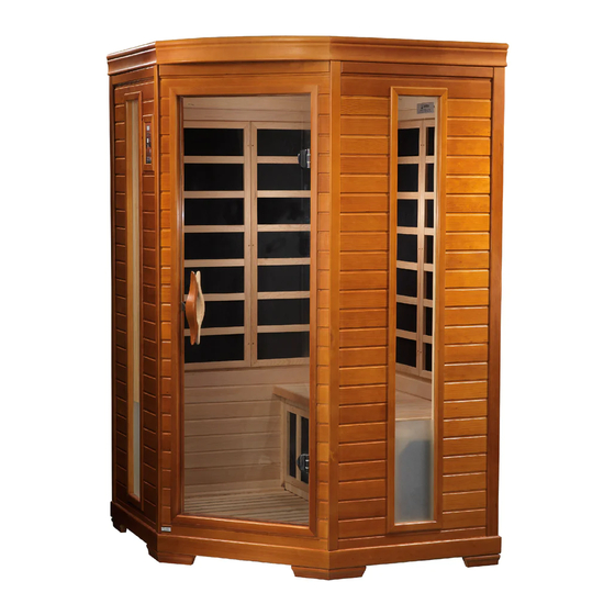
DYN6225 / DYN6235 / DYN6445 / DYN9235
2 ‐ 4 Person Corner Sauna
OWNER'S MANUAL
FOR CERAMIC AND CARBON MODEL SAUNAS
FOR INDOOR USE ONLY
120VAC 15 AMP (2-PERSON MODELS) DEDICATED CIRCUIT
120VAC 20 AMP (3 & 4 PERSON MODELS) DEDICATED CIRCUIT
Sauna: Now you can enjoy the European secret for youthful vitality.
Carefully and thoroughly read this manual before using the sauna. We
recommend keeping this manual for regular review and future reference.
Advertisement
Table of Contents

Related Manuals for Dynamic Saunas DYN6225


Summary of Contents for Dynamic Saunas DYN6225
- Page 1 DYN6225 / DYN6235 / DYN6445 / DYN9235 2 ‐ 4 Person Corner Sauna OWNER’S MANUAL FOR CERAMIC AND CARBON MODEL SAUNAS FOR INDOOR USE ONLY 120VAC 15 AMP (2-PERSON MODELS) DEDICATED CIRCUIT 120VAC 20 AMP (3 & 4 PERSON MODELS) DEDICATED CIRCUIT Sauna: Now you can enjoy the European secret for youthful vitality.
- Page 2 *PLEASE READ INSTRUCTIONS BEFORE ASSEMBLY* DYN-6225 GDI-6235 *The above assembly diagrams are quick reference visual guides only. All sauna models are not shown. Sauna models, parts, and accessories may vary.
- Page 3 WHAT ARE INFRARED RAYS? Infrared is the band of light we perceive as heat. We cannot see this band of light with the naked eye, but we can feel this type of light in the form of heat. Our sun produces most of its energy output in the infrared segment of the spectrum.
- Page 4 HOW IT WORKS Infrared Saunas differ from traditional saunas in that they use infrared radiant energy to directly penetrate into the body's tissue to produce perspiration. Traditional saunas use steam to heat the air inside the sauna, which then heats your body until you begin to perspire.
- Page 5 Benefits include, but are not limited to: - Pain relief from Rheumatoid Arthritis - Relaxing muscle spasms - Increases blood circulation - Cardiovascular conditioning - Clears rashes, acne - Reduces cellulite - Removes toxins and mineral waste - Reduces stress and fatigue - Enhances skin tone SAUNA MAINTENANCE Since infrared saunas do not require hot rocks, water, or steam to operate, they require very little...
-
Page 6: Table Of Contents
TABLE OF CONTENTS Product Introduction Parts Description Assembly Instructions Operating the Sauna Tips for Using Your Sauna Safety Instructions Safeguards for Your Sauna Troubleshooting Guide Warranty Warranty Card WARNING: Visually inspect all heaters before assembly to make sure they are not damaged. Any excessive vibrations during transport could cause damage to the heating elements. -
Page 7: Parts Description
PARTS DESCRIPTION A. FRONT OF SAUNA (see Figure 1) B. INSIDE OF SAUNA (see Figure 2) Figure 1 Figure 2 1) Control Panel 2) Door Handle 3) Tempered Glass Door 4) Glass Window Panel 5) Bench Panel 6) Bench Emitter Panel 7) Back Protection Grid (Ceramic Model Saunas Only) 8) Speaker 9) Ventilation Grid... - Page 8 I. Power Supply The POWER SUPPLY BOX is the control center of the sauna room. It is installed on the ROOF PANEL and has input/outputs connected to it as seen below. (see Figure 3) Figure 3 MAIN POWER main power of the sauna room HT1, HT2, HT3, HT4 emitter power output cords LIGHT...
- Page 9 III. Component Labeling POWER Power Cord HT1, HT2, HT3, HT4 Emitter (heater) power cords LIGHT Reading lamp connector ROOF LAMP Roof lamp connector (optional) COLOR LAMP Color lamp connector (optional) CTRL Control panel connector CD/SIG For CD/temperature sensor/buzzer/etc. connectors CD-POWER CD/radio power connector FAN- POWER CD/radio fan power connector...
- Page 10 Figure 6 V. Panel Descriptions For easier installation, please understand and distinguish the differences between each panel. A. Floor Panel When the floor panel faces upward, you will find (5) raised moldings with (3) notches. Three of the sides will have buckles. The front side will have no buckles. (see Figure 7) Figure 7 Understanding The Difference Between The Top And Bottom Of The Wall Panels The (2) rear panels are in the upright position when the vertical slot on the right rear panel (for the...
- Page 11 Figure 8 C. Rear Panels The length of the rear panels are almost the same as the floor panel length. If you are facing the front of the sauna, the rear panel with the aluminum label (located on the outside of one of the rear panels) will be your RIGHT SIDE REAR PANEL.
-
Page 12: Assembly Instructions
Assembly Instructions Choose a good location to assemble the sauna The location must be dry, leveled, and away from any source of water MAIN POWER cord must be easily accessible Two adults are required for installation Wood cabin installation order: Floor Panel Left Side Rear Panel Right Side Rear Panel Left Side Panel... - Page 13 Figure 11 Installing the LEFT and RIGHT SIDE PANELS Determine the correct placement of the LEFT and RIGHT SIDE PANELS by matching each end of the buckles on the LEFT SIDE and RIGHT SIDE PANELS with the buckles on the REAR PANELS.
- Page 14 Figure 14 Installing the BENCH EMITTER PANEL, BENCH PANEL and BENCHES Locate the (2) square wood frames that have two cutouts on one side and a vertical slot on the other side. Place one of the wood frames next to the glass window with the two cutouts facing the glass window and the vertical slot facing towards the front.
- Page 15 Installing the FRONT PANEL Place the FRONT PANEL onto the recessed area on the FLOOR PANEL. Align guides on the LEFT SIDE PANEL with the guide inserts on the FRONT PANEL. The LEFT SIDE PANEL will need to be lifted in order to lock the guide inserts on the LEFT SIDE PANEL into the guides on the FRONT PANEL.
- Page 16 Connecting the plugs on the ROOF PANEL Connect the plugs according to their respective labels. (see Figure 21 and Figure 22) Connect the CTRL plug from the power supply box to the CTRL plug from the control panel. Then screw together. (see Figure 23) Connect the buzzer connection.
- Page 17 Figure 25 Figure 26 Figure 27 K. Installing the CD/RADIO (optional) Unscrew the lock screws on the top of CD/RADIO player. Connect the plug from the CD/RADIO with the plug coming down from the roof. (see Figure Connect the left and right speaker plugs. (see Figure 29 and 30) Connect the antenna plug to the CD/RADIO player.
- Page 18 L. Installing the TEMPERATURE SENSOR Enter the sauna and remove the protective covering from the TEMPERATURE SENSOR. Situate the TEMPERATURE SENSOR so that it is vertical and pointing downward. (see Figure 32) Figure 32 Note: Some sauna models are shipped with a spare TEMPERATURE SENSOR in case the TEMPERATURE SENSOR is damaged during transit.
-
Page 19: Operating The Sauna
Operating the Sauna NOTE: Before the sauna is turned on, remove plastic protective covering from the CONTROL PANELS. Please check and confirm that the connections to the POWER SUPPLY, HEAT EMITTERS, CD/RADIO, and TEMPERATURE SENSOR are connected properly. The power supply voltage and frequency must match the requested voltage and frequency of the sauna (120VAC 15AMP Dedicated Circuit or 120VAC 20AMP Dedicated Circuit). - Page 20 7. Reading lamps and/or roof lamps and/or color therapy lamps are operated by pressing the respective buttons located towards the center of the control panel. These lamps are offered on some models and are not available on all models. 8. Chromotherapy/Color Therapy Lighting (optional) can be operated as follows. First, you will need to install the battery.
-
Page 21: Tips For Using Your Sauna
CONTROL PANEL Power On/Off: Press to control the main power of the sauna Power Indicator: Indicates the status of the sauna’s main power Work Start/Stop: Press to control the working functions of the sauna Work Indicator: Indicate the working status of the sauna Heat Indicator: Indicate the status of heating function Light: Press to control the lighting function Time Display: Display the heating time of the sauna in minutes... -
Page 22: Safety Instructions
5) At the first sign of a cold or flu, increasing your sauna sessions may be beneficial in boosting your immune system and decreasing the reproductive rate of viruses. 6) To help relieve sore and tense muscles, massage the affected areas during your sauna session. 7) To treat your ankles and feet more effectively, you can elevate them and move them close to one of the heat emitters to achieve a deep heating effect. -
Page 23: Safeguards For Your Sauna
16) Do not continuously switch the power on and off as it will compromise the life of the electrical components. 17) Your hands must be dry and free of moisture before plugging and unplugging cords and wiring harnesses from the power supply and circuit boards. Never operate the sauna with wet hands or wet feet to avoid risk of electric shock. - Page 24 “TEMP SENSOR” (you just connected) down the vent on the roof so that it is now inside the sauna. Then go to the control panel and press the power button. If the heat emitters now have heat, then the “TEMP SENSOR” was the cause of the problem. You may have to wait about five minutes to confirm if the heat emitters are generating heat.
-
Page 25: Warranty
Limited Lifetime Warranty 5 Year Limited Warranty: Golden Designs, Inc. warranties the wood, structure, heating elements, and electronics against defects in material and workmanship for a period of 1 to 5 years from the original date of purchase. This sauna is for INDOOR use only. Placing your sauna outdoors will VOID this warranty. - Page 26 PAGE INTENTIONALLY LEFT BLANK...
-
Page 27: Warranty Card
WARRANTY CARD Congratulations on your purchase of an Infrared Sauna from Golden Designs, Inc. Please take the time to complete the following Warranty Card and mail it back to: Golden Designs, Inc. 1920 Proforma Ave. Ontario, CA 91761 Please include a copy of your sales receipt showing date of purchase as this will serve as proof of purchase.
Need help?
Do you have a question about the DYN6225 and is the answer not in the manual?
Questions and answers