Advertisement
R E P L A C I N G T H E P R I N T H E A D
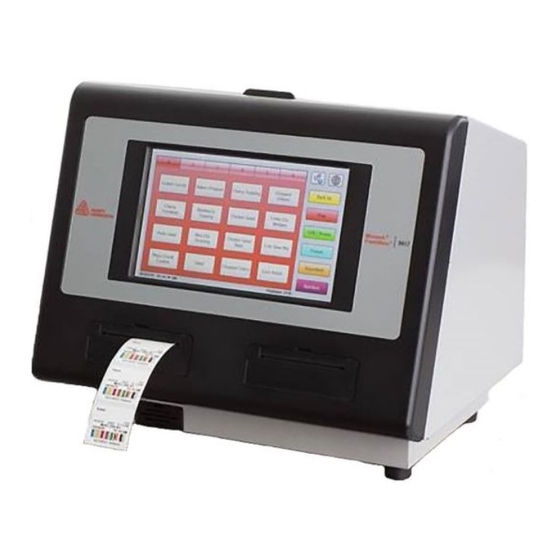
Use these instructions to replace the printhead assembly in the 9417 Printer.
A u d i e n c e
These instructions are intended for a skilled service
technician only. For additional information or
assistance, call Service at 1-800-543-6650.
C a u t i o n s
♦
The 9417 printer contains devices that are
sensitive to electrostatic discharge (ESD); failure
to exercise caution can damage the printer. We
recommend using an ESD wrist strap, grounding
mat, or grounding workbench when performing
maintenance on the printer.
♦
Flex connectors between components and board
assemblies are extremely fragile; when damaged,
they require component or board assembly
replacement.
R e q u i r e d T o o l s
The procedures require the following:
♦
A hard, dry surface to set the printer on
♦
Phillips screwdriver
R e m o v i n g t h e P r i n t h e a d
1. Turn off the printer and unplug it from the electrical outlet.
2. Open the front cover.
3. Remove the supplies.
4. Remove the six screws that attach the print module covers.
5. Lift up the right then left printer cover; rest them out of the way.
Avery Dennison® is a registered trademark of Avery Dennison Corporation.
TC9417PHI Rev. AB 6/15
©2013 Avery Dennison Corp. All Rights Reserved.
Advertisement
Table of Contents

Subscribe to Our Youtube Channel
Related Manuals for Avery Dennison 9417


Summary of Contents for Avery Dennison 9417
- Page 1 R E P L A C I N G T H E P R I N T H E A D Use these instructions to replace the printhead assembly in the 9417 Printer. A u d i e n c e These instructions are intended for a skilled service technician only.
- Page 2 6. Lift out the printhead assembly. 7. Open the four black flex connector latches. Remove the flex from the flex connector Flex Connec tor Lat ch Note: Apply careful, even pressure on the latches when opening and closing. I n s t a l l i n g t h e P r i n t h e a d Make sure the four black flex connector latches are open, then insert the printhead flex into the flex connector.
- Page 3 Lay the left print module cover in place then lay the right print module cover in place. Secure the printer covers in place. Replacing the Printhead...
Need help?
Do you have a question about the 9417 and is the answer not in the manual?
Questions and answers