Table of Contents

Related Manuals for Matrix SDT 5000


Summary of Contents for Matrix SDT 5000
- Page 1 Satellite Data Terminal SDT 5000 User Manual Wireless Matrix Corporation Document MBUD-0109v1 12369-B Sunrise Valley Drive, Reston, VA 20191 Version 1.1 Phone : (703) 262-0500 March 24, 2006 FAX : (703) 262-0380 www.wirelessmatrixcorp.com...
- Page 2 Important Safety Precautions The SDT 5000 has complex hardware and software, and it is important to consider the consequences of unexpected or abnormal behavior, which may be caused by a human failure to comprehend, inadequate documentation, a software error or defect. When the consequences of a failure mode are serious, it is essential to protect life and property against such a failure by means of redundant back- up systems or safety devices.
- Page 3 Safety Information section of this guide. This could result in personal injury. Do NOT operate the SDT 5000 unit in areas where explosives are in use as the RF frequency could interfere with the operation, causing hazardous conditions. Do NOT operate the SDT 5000 unit in areas where two-way radio communications is prohibited.
-
Page 4: Table Of Contents
ARDWARE NSTALLATION ....................... 9 SING THE 2.5.1 Test Port Screens ........................9 2.5.2 Test Port Command line ..................... 12 SDT 5000 QUICK START ......................14 RTU P ..........................14 3.1.1 Transparent Mode....................... 14 3.1.2 AT Mode..........................16 3.1.3 Narrowband Protocol (NBP) Mode ..................17 ............................ - Page 5 11. COMMAND SERVER FACILITY ................... 52 APPENDIX A – PHYSICAL DIMENSIONS .................. 53 APPENDIX B – SDT 5000 ELECTRICAL CONNECTIONS ............54 APPENDIX C – SDT 5000 TEST PORT PINOUT ................. 56 APPENDIX D – ASCII CODE CHART ..................57 APPENDIX E – GLOSSARY......................58 Version 1.1, 03/24/06...
-
Page 6: List Of Figures
SDT 5000 User Manual Document MBUD-0109v11 List of Figures 1 - T SDT 5000 ..........6 IGURE YPICAL POLE MOUNTED COMMUNICATOR UNIT 2 - MSAT S ....................22 IGURE YSTEM IAGRAM 3 - I SDT 5000 MET..............24 IGURE... -
Page 7: List Of Tables
SDT 5000 User Manual Document MBUD-0109v11 List of Tables 1 – S SDT 5000................23 ABLE ADDRESSING FOR THE Version 1.1, 03/24/06 Page vii... -
Page 8: List Of Screens
SDT 5000 User Manual Document MBUD-0109v11 List of Screens 1 - L ........................10 CREEN OGON SCREEN 2 - I ...................... 11 CREEN NSTALLATION CREEN 3 - B ..................... 47 CREEN ASIC SCREEN COMPONENTS Version 1.1, 03/24/06 Page viii... -
Page 9: Introduction
Document MBUD-0109v11 1. INTRODUCTION Wireless Matrix thanks you for choosing the SDT 5000 for your remote data communication solution. We hope it will be a valuable asset in your operations for many years to come. The SDT 5000 is an integrated, lightweight, highly ruggedized satellite data transceiver (SDT). It is highly configurable, with a user-friendly interface. -
Page 10: Reference Documents
Numerous options are available to provide non-volatile memory, Ethernet and other features. 1.2 Reference Documents The following documents may also be required depending on the operating mode of the SDT 5000: • MAN002 SDT 5000 Command Reference, Wireless Matrix Corp •... -
Page 11: Contacting Wireless Matrix
Wireless Matrix welcomes your comments and suggestions regarding your SDT 5000 and this manual. For servicing and technical support, users should contact the Value Added Reseller (VAR) who provided the SDT 5000. If your VAR was unable to satisfactorily resolve your technical issue, you may contact us directly. -
Page 12: Setup And Installation
Document MBUD-0109v11 2. SETUP AND INSTALLATION This section describes how to install and test your SDT 5000. Please read the following chapter carefully before attempting any installations. Also please read and understand the section “How to use the Screens” before attempting installation. -
Page 13: Site Selection
FAST BLOW (PART NUMBER: LITTLEFUSE 217005 or 217005XP or F5AL250V). 2.3 Site Selection Your SDT 5000 assembly has been thoroughly tested and designed for use in rugged weather conditions and Class I Division II environments. However, due care and attention is still required for a proper installation. -
Page 14: Hardware Installation
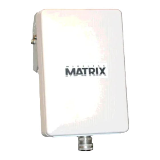
Interface Cable Figure 1 - Typical pole mounted SDT 5000 communicator unit. The SDT 5000 is supplied with a pole-mounting bracket, which mounts on a 2 inch to 2.5 inch diameter pole. Ensure your mounting pole is securely fastened. 2.4 Hardware Installation This section describes the physical connections required to install the SDT 5000. - Page 15 Connect the 12 Volt power supply or battery to the SDT 5000 via the interface cable conductors (See Appendix B for details). With power applied and the ignition line is asserted (ignition line connected to 12V or Switch J4 ‘on’) the SDT 5000 should start and the VT100 terminal will...
- Page 16 8 SS: Task WD-1, id 0x3d4e58, pri 127, msg 2, tcb 3d4ebc The SDT 5000 will boot and run a series of self-diagnostic tests. Once the unit has completed the start up procedures (approximately. 5 seconds) the antenna aiming procedure from section 2.5.1.3 should be followed.
-
Page 17: Using The Test Port
The test port provides diagnostic information through the test port. Most diagnostic messages provide a time stamp followed by a text message. The text messages provide information about various facilities in the SDT 5000. The next sections provide a brief usage of the Test Port. - Page 18 2.5.1.3 Installation Screen 1. Aim the antenna while in the Installation screen only. 2. The direction that the antenna must be aimed will depend on the SDT 5000’s geographic location. From North America, the antenna should initially be pointed in a southerly direction.
- Page 19 7. Enter “E <ENTER>” to exit the installation screen. After exiting the installation screen if the SDT 5000 has never been commissioned, it will automatically commission on the MDS system. (The unit must be in Sync, and SASK and MUI information must have been entered by the VAR).
-
Page 20: Test Port Command Line
2.5.2.2 Login command The login command allows the user to sign into the SDT 5000. There are various login privilege levels. The user will most often need to login as “user” level. NILL> login user user USER>... - Page 21 SDT 5000 User Manual Document MBUD-0109v11 This will display all possible commands available at the current privilege level. USER> help a This will display the commands available at the current privilege level, which start with the letter ‘a’. USER>help log...
-
Page 22: Sdt 5000 Quick Start
5000. 3.1 RTU Port The RTU port is, as the name suggests, the SDT 5000 serial port to which the RTU is connected. The RTU port supports several application modes of operation: Transparent Protocol Mode, AT Mode, PPP Mode and Narrowband Protocol Mode. - Page 23 • The SDT 5000 is now ready to send messages to the host. Have the RTU (or use a terminal) to send data in the RTU port. After several seconds, the data should arrive at the host.
-
Page 24: At Mode
• DTR must be asserted to communicate with the RTU port. • The SDT 5000 is now ready to communicate with the host. The RTU can establish a connection to the host using the standard AT command sequence: atd316520020034 CONNECT 9600 •... -
Page 25: Narrowband Protocol (Nbp) Mode
• The RTU can, via a Narrowband protocol primitive, request a connection with the host. • When the SDT 5000 indicates that the connection is successful the RTU can send data to the host. • The data should arrive at the host after several seconds. The delay is due to the propagation delay through the satellite. -
Page 26: Events
The ‘ignition’ event is generated in response to changes to the ignition input. The ignition line is used to control power to the SDT 5000. This event can be active high or active low. A clear message can be sent. -
Page 27: Common Event Parameters
SDT 5000 User Manual Document MBUD-0109v11 3.2.2 COMMON EVENT PARAMETERS The events are controlled with a number of common parameters including: action, X25 destination address, UDP/IP address and port, acknowledge required flag, maximum number of buffered alarms, retry timeout, maximum retries, acknowledge required, buffer alarm flag, connection hold time, and message wait time. -
Page 28: Event Commands
The syntax is: >evtuser See the SDT 5000 command reference for details on these commands. 3.2.5 MESSAGE FORMATS The first byte is the message identifier. All multibyte values are big-endian format with the exception of the CRC values that are little endian. -
Page 29: Output Signal Connections
The CRC value is stored as “little endian”. 3.3 Output Signal Connections The SDT 5000 support three output signals. The signals are a low side driver, high side driver, and a Pulse Width Modulated (PWM) output. The low side driver can sink up to 200 mA. The low side driver is controlled with the command ”output”, when the low side driver is on it will sink current (pull down). -
Page 30: System Overview
8208 specification. X25 allows for bi-directional data flow to the host from the RTU and from the host to the RTU. The SDT 5000 is assigned an X25 address from the service provider. This address is available with the command: >x25dnic... -
Page 31: Hardware Overview
The destination (host) address must be obtained from the host administrator of the system you wish to connect. Note: The SDT 5000 will ignore all packets that have the Q bit or A bit set to 1. For details on the Q- bit or A-bit refer to the ISO 8208 specification. -
Page 32: Figure 3 - Internal Block Diagram Of Sdt 5000 Met
SDT 5000 User Manual Document MBUD-0109v11 Expansion MiniMET Board Transceiver SDT5000 Fuse Terminal Blocks Test Port Vent Conduit Figure 3 - Internal block diagram of SDT 5000 MET. Version 1.1, 03/24/06 Page 24... -
Page 33: Hardware Interfaces
The ignition line is connected to pin 2 (IGN) of J2. This input is driven to VBAT to maintain power to the SDT 5000. The ignition line does not need to be connected if switch J4 is set to the ON position. -
Page 34: Outputs
SDT 5000 User Manual Document MBUD-0109v11 Ohms and a contact to ground may be used to drive these inputs. The minimum input voltage to be declared as high is 2.4 Volts. The maximum input voltage to be declared low is 0.2 Volts. -
Page 35: High Side Driver Output
SDT 5000 User Manual Document MBUD-0109v11 5.4.2 HIGH SIDE DRIVER OUTPUT The high side driver output is connected to pin 14 (OUT 2) of J5. The high side driver will pull the signal to VBAT when active. The high side driver output can source up to 200 mA of current. -
Page 36: Reserved Pins
SDT 5000 User Manual Document MBUD-0109v11 5.6 Reserved Pins Pins 25 through 32 inclusive usage depends on optional configuration of the SDT 5000 with an expansion card. Version 1.1, 03/24/06 Page 28... -
Page 37: Rtu Port
Messages from the host to the RTU are unconstrained in length. Messages from the RTU to the SDT 5000 may be up to 8 Kbytes long. Messages from the host to the RTU are not buffered and are transmitted as they are received. If the flow control prevents the data from being sent to the RTU the X25 data packets will not be acknowledged and the connection will timeout. - Page 38 A nonvolatile option is available for the SDT 5000 which provides 32 Kbytes of storage for the RTU originated data. If the nonvolatile storage is not used the RTU data is lost when the SDT 5000 is powered down or reset.
- Page 39 RTU from sending unsolicited data to the host. The host can still connect to the SDT 5000 and send and receive data from the RTU. If the buffer message flag is YES any data sent by the RTU will be buffered until the host connects.
- Page 40 SDT 5000 User Manual Document MBUD-0109v11 End of message idle The end of message idle timer is used to terminate a message based on the timer inter-character timeout. If no character is received for more than the end of message timer the message is terminated. The end of message idle timer is measured in seconds with 1 decimal place.
- Page 41 The default value is NO. RTU buffer message If the RTU data must be buffered by the SDT 5000 even when the data cannot be sent to the host the RTU buffer message flag must be set to YES. If the RTU buffer message flag is set to NO the data will be discarded after the number of retries has been exceeded.
- Page 42 NONE. If the RTU bound flow control is set to RTS when RTS is dropped the SDT 5000 stops sending data to the RTU. When the RTU RTS is raised the SDT 5000 resumes sending data to the RTU.
- Page 43 If the DCD mode is CONNECTED the DCD line on the RTU port will be asserted when the SDT 5000 has a connection with the host. Data set ready (DSR) The DSR mode controls the output of DSR with the following values:...
-
Page 44: At Command Mode
Messages from the host to the RTU are not constrained in length. The data is sent to the RTU as each X25 packet of data is received by the SDT 5000, regardless of the M bit. Messages from the RTU to the SDT 5000 are not constrained in length, as a complete packet of data is received by the SDT 5000 the data is sent to the host. - Page 45 If the DCD mode is CONNECTED the DCD line on the RTU port will be asserted when the SDT 5000 has a connection with the host. The user via the AT&CN command on the RTU port may modify this value.
-
Page 46: Narrowband Protocol (Nbp) Mode
Messages from the host to the RTU are not constrained in length. The data is sent to the RTU as each X25 packet of data is received by the SDT 5000, regardless of the M bit. Messages from the RTU to the SDT 5000 are not constrained in length, as a complete packet of data is received by Version 1.1, 03/24/06... - Page 47 SDT 5000 User Manual Document MBUD-0109v11 the SDT 5000 the data is sent to the host. Messages are delimited by the RTU by sending a packet without the M bit set. The Narrowband Protocol is defined in: NBP Programmers Guide available from Wireless Matrix Corp.
- Page 48 SDT 5000 User Manual Document MBUD-0109v11 off when idle. For more information please see section 8, Power Modes. Narrowband The Narrowband protocol ack timeout defines the maximum time to wait protocol ack for an acknowledge after sending a data packet. The default value is 5 timeout seconds (5000 mS).
-
Page 49: Optional Ethernet Port
7. OPTIONAL ETHERNET PORT The SDT 5000 can be configured with a factory option to provide a 10 Base-T Ethernet port. The Ethernet port can be used as either a host connection or an RTU interface. The interface is wired as a standard medium dependant interface (MDI). -
Page 50: Power Modes
Power off mode is requested by deasserting the ignition line. The SDT 5000 is not running when in power off mode and must be powered on with the ignition line to resume operations. All RTU data will be ignored when in power down mode. -
Page 51: Continuous Mode
In Standby mode the processor is active but the transceiver is off. Standby mode is generally the most power efficient mode that does not lose RTU data. The SDT 5000 will draw less than 20 mA while sleeping. The total power consumed will depend on the duty cycle of sleep time to wake time. -
Page 52: Figure 7 - Polled Mode Operation
SDT 5000 User Manual Document MBUD-0109v11 Unlike Standby mode, scheduled events do not automatically turn on the transceiver. The transceiver is only turned on based on outgoing calls or the poll interval. The duty cycle is based on the underlying communication retries such that the wake period will correspond with one of the communication retries. -
Page 53: Sdt 5000 Operational States
On startup up the SDT 5000 will transition through several other states before reaching the “Operational” state. Channel Search In this state, the SDT 5000 is tuning to the various Data Hub (DH) frequencies it knows, looking for a valid signal. This mode will occur under the following conditions: •... - Page 54 MET fails commissioning the Data Hub will set the MET to “MET Deactivated”. Logon Pending Every time the SDT 5000 crosses satellite beams, it is required to logon to the MDS network again. This process is entirely automatic and the SDT 5000 will normally be in this state for only a very short time.
-
Page 55: How To Use The Screens
10. HOW TO USE THE SCREENS 10.1 Basic Screen Components The user can interact locally with the SDT 5000 through a set of screens accessible through the TEST port. While the function and form of the screens can vary greatly, every screen was designed to operate in exactly the same way. -
Page 56: Screen Body
SDT 5000 User Manual Document MBUD-0109v11 The Selection Bar is displayed using reverse video characters, while the selection with the cursor is displayed with normal video characters. 10.1.3 SCREEN BODY The Screen Body is the main viewing area on each screen and is located from line 4 to line 22. -
Page 57: Information Field
Section 9, SDT 5000 Operational States. Sync The SDT 5000 may be in SYNC or in the NO SYNC state with relation to the Data Hub (DH) signal, or it may be in PILOT state. If the Sync state is SYNC then the SDT 5000 is synchronized with the Data Hub and is receiving the Data Hub signal. -
Page 58: Using The Keyboard
SDT 5000 User Manual Document MBUD-0109v11 Tx indicator TX is displayed when the unit is transmitting data over the satellite. 10.2 Using the Keyboard The screen manager allows for some powerful edit capabilities. The following is a list of all the keys that are recognized. -
Page 59: Selection Overview
SDT 5000 User Manual Document MBUD-0109v11 <UP ARROW> While in numeric Edit Fields the current value of the field is incremented by one. While in enumerated fields with predefined values, advance to the next value. 10.3 Selection Overview Commands and Selection Numbers (called commands for the rest of this section) are issued from the Select Field. -
Page 60: Command Server Facility
Display the software version strings. The SDT 5000 recognizes spaces as the end of parameter, command or string. If you wish to insert a space inside a string, you must enclose the string within quotation marks (i.e. “ string with spaces”). -
Page 61: Appendix A - Physical Dimensions
SDT 5000 User Manual Document MBUD-0109v11 APPENDIX A – PHYSICAL DIMENSIONS 3/4" NPT 2.25" 13.00" 7.8" OUTSIDE DIMENSIONS FOR SDT5000 Version 1.1, 03/24/06 Page 53... -
Page 62: Appendix B - Sdt 5000 Electrical Connections
SDT 5000 User Manual Document MBUD-0109v11 APPENDIX B – SDT 5000 ELECTRICAL CONNECTIONS The following diagram shows the standard SDT 5000 interface connection: SDT5000 CONNECTION GUIDE (STANDARD) POWER & IGN RS232 TEST PORT RS232 ANALOG INPUT 0-5V DIGITAL INPUT (VBAT MAX) - Page 63 SDT 5000 User Manual Document MBUD-0109v11 The following diagram shows the interface connections for the SDT 5000 with Ethernet option: SDT5000 CONNECTION GUIDE (RJ45 OPTION) POWER & IGN RS232 TEST PORT RS232 ANALOG INPUT 0-5V DIGITAL INPUT (VBAT MAX) ETHERNET...
-
Page 64: Appendix C - Sdt 5000 Test Port Pinout
SDT 5000 User Manual Document MBUD-0109v11 APPENDIX C – SDT 5000 TEST PORT PINOUT The following diagram shows the Test Port RS232 connector pinout: SEE DETAIL 'A' RSSI DETAIL 'A' WIRE CONNECTOR PIN # SIGNAL TYPE OUTPUT INPUT OUTPUT RSSI... -
Page 65: Appendix D - Ascii Code Chart
SDT 5000 User Manual Document MBUD-0109v11 APPENDIX D – ASCII CODE CHART Symbol Symbol Symbol Symbol “ & ‘ XOFF < > Version 1.1, 03/24/06 Page 57... -
Page 66: Appendix E - Glossary
Machine Identification Number used to identify all Wireless Matrix products. MSAT Acronym for Mobile Satellite, and in the context of the SDT 5000 product will normally refer to the MSAT Packet Data Service provided by a network operator. MDS User Identification provided by the system provider and entered a unit by the VAR. - Page 67 Standby Mode A low power mode in which the SDT 5000 has powered down and is waiting for an event to wake it up. Wakeup events include a scheduled event, an alarm input, or DTR asserted on the RTU port.
Need help?
Do you have a question about the SDT 5000 and is the answer not in the manual?
Questions and answers