Table of Contents
Advertisement
Quick Links
This user's guide describes the operation of the evaluation module for the DRV604. The user's guide also
provides measurement data and design information like schematic, BOM and PCB layout.
.....................................................................................................................
1
2
3
4
5
6
7
8
1
2
3
2
4
5
6
DirectPath, FilterPro are trademarks of Texas Instruments.
SLOU288 - February 2010
Submit Documentation Feedback
DRV604PWPEVM
..........................................................................................................
............................................................................................................
.......................................................................................................
.................................................................................................
..........................................................................................
....................................................................................................
List of Figures
............................................................................................
...............................................................................................
..............................................................................
.........................................................................................
..................................................................................
....................................................................................
Copyright © 2010, Texas Instruments Incorporated
DRV604PWPEVM
Contents
.....................................................................
User's Guide
SLOU288 - February 2010
2
4
4
5
7
7
15
16
3
4
5
9
9
10
1
DRV604PWPEVM
Advertisement
Table of Contents

Related Manuals for Texas Instruments DRV604PWPEVM


Summary of Contents for Texas Instruments DRV604PWPEVM
-
Page 1: Table Of Contents
Order Active Low-Pass Filter, SE Input ..................THD+N vs Voltage (Line Output) .................. THD+N vs Power (HeadPhone Output) ..................THD+N vs Frequency (Line Output) DirectPath, FilterPro are trademarks of Texas Instruments. SLOU288 – February 2010 DRV604PWPEVM Submit Documentation Feedback Copyright © 2010, Texas Instruments Incorporated... -
Page 2: Overview
......................Bill of Materials Overview The DRV604PWPEVM customer evaluation module demonstrates the DRV604PWP integrated circuit (IC) from Texas Instruments (TI). The DRV604PWP is a 2Vrms Pop-Free stereo line driver with a stereo headphone driver designed to allow the removal of the output DC-blocking capacitors for reduced component count and cost. The device is ideal for single supply electronics where size and cost are critical design parameters. -
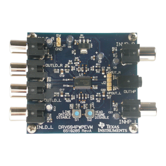
Page 3: Drv604Pwpevm Evm Photo
DVD mini-component systems, home theater in a box (HTIB) or soundcards This document covers EVM specifications, audio performance measurements graphs, and design documentation that includes schematics, parts list and layout design. Figure 1. DRV604PWPEVM EVM Photo Gerber (layout) files are available at www.ti.com. DRV604PWPEVM Features The DRV604PWPEVM has these features: •... -
Page 4: Quick Setup Guide
On opening the DRV604PWPEVM package, ensure that the following items are included: • 1 pc. DRV604PWPEVM board using one DRV604PWP. If either of these items is missing, contact the Texas Instruments Product Information Center nearest you to inquire about a replacement. Power-Supply Setup To power up the EVM one power supply is needed. -
Page 5: Component Selection
MFB with single ended input. Further the DRV604 needs an AC-coupling capacitor to remove dc-content from the source. DRV604 Figure 3. 2 Order Active Low-Pass Filter, SE Input SLOU288 – February 2010 DRV604PWPEVM Submit Documentation Feedback Copyright © 2010, Texas Instruments Incorporated... -
Page 6: Drv604Pwpevm Filter Specifications
The component values can be calculated with the help of the TI FilterPro™ program available on: http://focus.ti.com/docs/toolsw/folders/print/filterpro.html Table 3 various proposals for the filter and gain settings can be found. Table 3. DRV604PWPEVM Filter Specifications C10, C15, C7, C12 C9, C14,... -
Page 7: Layout Recommendations
Output voltage, 100 kΩ 2.2 Vrms 1 kHz, 1% THD+N, T = 25°C Supply current < 30 mA 1 kHz, 40mW at 32 Ω and 2Vrms at 5 kΩ SLOU288 – February 2010 DRV604PWPEVM Submit Documentation Feedback Copyright © 2010, Texas Instruments Incorporated... -
Page 8: Audio Performance Line Output
65 × 60 × 25 mm Width × Length × Height (mm) Total weight 34 gr Components + PCB + Mechanics Note: All electrical and audio specifications are typical values DRV604PWPEVM SLOU288 – February 2010 Submit Documentation Feedback Copyright © 2010, Texas Instruments Incorporated... -
Page 9: Thd+N Vs Voltage (Line Output)
Load = 32 W In Phase Out of Phase 0.05 0.01 0.005 0.002 0.001 100m Power - W Blue: 32 Ω Figure 5. THD+N vs Power (HeadPhone Output) SLOU288 – February 2010 DRV604PWPEVM Submit Documentation Feedback Copyright © 2010, Texas Instruments Incorporated... -
Page 10: Thd+N Vs Frequency (Line Output)
0.01 0.005 20 mW 0.002 0.001 f - Frequency - Hz Green 2mWrms Blue: 20mWrms Load Impedance is 32Ω Figure 7. THD+N vs Frequency (HeadPhone Output) DRV604PWPEVM SLOU288 – February 2010 Submit Documentation Feedback Copyright © 2010, Texas Instruments Incorporated... -
Page 11: Fft Spectrum With -60-Dbfs Tone (Line Output)
Vertical spacer -100 -120 -140 10 k 15 k 20 k f - Frequency - Hz Figure 9. FFT Spectrum with –60-dBFS Tone (Head-Phone Output) Vertical spacer SLOU288 – February 2010 DRV604PWPEVM Submit Documentation Feedback Copyright © 2010, Texas Instruments Incorporated... -
Page 12: Channel Separation, Line Output
Left to Right -100 f - Frequency - Hz Comments: Green: 0dB (40mWrms) Blue: Left to right Red: Right to left Figure 11. Channel Separation, Headphone Output DRV604PWPEVM SLOU288 – February 2010 Submit Documentation Feedback Copyright © 2010, Texas Instruments Incorporated... -
Page 13: Frequency Response, Line Output
DRV604PWPEVM Performance www.ti.com Frequency Response 200k f - Frequency - Hz 1Vrms output, 10kΩ load, 500kHz measurement filter, 2Vrms reference Figure 12. Frequency Response, Line Output SLOU288 – February 2010 DRV604PWPEVM Submit Documentation Feedback Copyright © 2010, Texas Instruments Incorporated... -
Page 14: Pop/Click (Enable)
Shown with and without input signal applied. The measurement results are presented in time domain. Load 5 kΩ Enable Enable Output 2 V/div Output 100 mV/div Figure 14. Pop/Click (Disable) DRV604PWPEVM SLOU288 – February 2010 Submit Documentation Feedback Copyright © 2010, Texas Instruments Incorporated... -
Page 15: Related Documentation From Texas Instruments
Related Documentation from Texas Instruments Table 9 contains a list of data manuals that have detailed descriptions of the integrated circuits used in the design of the DRV604PWPEVM. The data manuals can be obtained at the URL http://www.ti.com. Table 9. Related Documentation Part Number... -
Page 16: Design Documentation
Design Documentation www.ti.com Design Documentation Schematics Figure 15. DRV604PWPEVM Schematic: DRV604 DRV604PWPEVM SLOU288 – February 2010 Submit Documentation Feedback Copyright © 2010, Texas Instruments Incorporated... -
Page 17: Bill Of Materials
NEWARK SWITCHCRAFT INLD_R, OUTLD_L STX-3000 OUTHP 806-STX-3000 JACK,MINI-STEREO,ROHS MOUSER KYCON SWITCHES TL1015AF160QG S1, S2 EG4344CT SWITCH, MOM, 160G SMT 4×3MM ROHS DIGI-KEY E-SWITCH COMPONENTS NOT ASSEMBLED SLOU288 – February 2010 DRV604PWPEVM Submit Documentation Feedback Copyright © 2010, Texas Instruments Incorporated... -
Page 18: Drv604Pwpevm Pcb Component Placement
Design Documentation www.ti.com PCB Layers Gerber files are available on the EVM page for download Figure 16. DRV604PWPEVM PCB Component Placement Figure 17. DRV604PWPEVM PCB Top Layer Figure 18. DRV604PWPEVM PCB Bottom Layer DRV604PWPEVM SLOU288 – February 2010 Submit Documentation Feedback... - Page 19 EVALUATION BOARD/KIT IMPORTANT NOTICE Texas Instruments (TI) provides the enclosed product(s) under the following conditions: This evaluation board/kit is intended for use for ENGINEERING DEVELOPMENT, DEMONSTRATION, OR EVALUATION PURPOSES ONLY and is not considered by TI to be a finished end-product fit for general consumer use. Persons handling the product(s) must have electronics training and observe good engineering practice standards.
- Page 20 IMPORTANT NOTICE Texas Instruments Incorporated and its subsidiaries (TI) reserve the right to make corrections, modifications, enhancements, improvements, and other changes to its products and services at any time and to discontinue any product or service without notice. Customers should obtain the latest relevant information before placing orders and should verify that such information is current and complete.
Need help?
Do you have a question about the DRV604PWPEVM and is the answer not in the manual?
Questions and answers