
Related Manuals for AXIOMTEK GOT815L-511


Summary of Contents for AXIOMTEK GOT815L-511
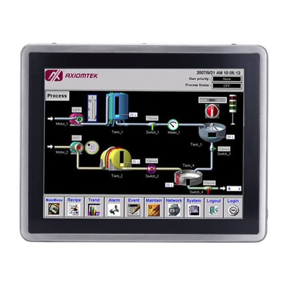
- Page 1 GOT815L-511 15” XGA TFT Touch Panel Computer User’s Manual IP69K certification distinguishes the highest level of reliability.
-
Page 2: Disclaimers
Axiomtek does not make any commitment to update the information in this manual. Axiomtek reserves the right to change or revise this document and/or product at any time without notice. -
Page 3: Safety Precautions
When handling boards and components, wear a wrist-grounding strap, available from most electronic component stores. Trademarks Acknowledgments Axiomtek is a trademark of Axiomtek Co., Ltd. IBM, PC/AT, PS/2, VGA are trademarks of International Business Machines Corporation. ® ™... -
Page 4: Table Of Contents
USB Port ..............10 2.1.4 DC Power Jack w/ M12 connector ......10 Water-proof Cables ........11 2.2.1 Power cable .............. 11 2.2.2 Power adapter for GOT815L-511 ......12 2.2.3 COM ................12 2.2.4 USB cables ............... 13 Mounting Method ........13 2.3.1 VESA mounting ............ - Page 5 This page is intentionally left blank.
-
Page 7: Chapter 1 Introduction
OS, such as W indows® 10 IoT embedded. For storage device, the GOT815L-511 supports 2.5” SSD or 2.5” SATA HDD device. Industrial-grade Product Design The GOT815L-511 has an incredible design to be used in different industrial environments. The whole enclosure meets the IP66 standard. -
Page 8: Specifications
GOT815L-511 User’s Manual Specifications 1.2.1 Main CPU Board ® Intel Core i5-7300U 3.5GHz processor onboard (Kaby Lake) System Memory One 260-pin DDR4-2133 SO-DIMM socket Maximum memory up to 16GB BIOS America Megatrends UEFI BIOS 1.2.2 I/O System... -
Page 9: System Specification
5 to 500 Hz, 1.0 G, random for 2.5” SSD 1. All specifications and images are subject to change without notice. 2. The GOT815L-511 is suited on serious environment; please choose the wide temperature DRAM and SSD. Note ℃... -
Page 10: Dimensions
GOT815L-511 User’s Manual Dimensions This diagram shows you dimensions and outlines of the GOT815L-511. Introduction... -
Page 11: I/O Outlets
GOT815L-511 User’s Manual I/O Outlets Please refer to the following illustration for I/O locations of the GOT815L-511. Function Backlight ON/OFF Brightness Adjust +/- Power ON/OFF DC Power Connector Ethernet COM1 (RS-232/422/485, default RS-232) COM2 (RS-232/422/485, default RS-232) USB 2.0 x 2 USB 2.0 x 2... -
Page 12: Antenna Installation (Optional)
GOT815L-511 User’s Manual Antenna Installation (Optional) If you have the optional wireless module, you will find the antenna in the accessory box. The installation instructions are as follows : 1. If you add optional 2T2R W IFI module, the ANT1 is MAIN wifi antenna, the ANT2 is AUX wifi antenna. -
Page 13: Package List
Water-proof Power / USB / LAN / RS-232 cables (optional) Water-proof Antenna for Wifi or UMTS/HSPA+ (optional) VESA ARM(optional) If you can not find the package or any items are missing, please contact Axiomtek distributors immediately. Introduction... -
Page 14: Chapter 2 System Configurations
GOT815L-511 User’s Manual CHAPTER 2 System Configurations The GOT815L-511 provides rich I/O ports and flexible expansions for you to meet different demand. The chapter will show you how to install the hardware. It includes: I/O Pin Assignment Hard Disk and DRAM ... - Page 15 GOT815L-511 User’s Manual Table 2: Jumpter setting for JP3 Function Setting +5V Power 1-3 close DCD Data: 3-5 close (Default) +12V Power 2-4 close RI Data: 4-6 close (Default) Warning: According the warrantee is adopt for the IP66 guarantee, please inform the COM1 setting when ordering, also please kindly don’t disassemble the system by...
-
Page 16: Ethernet
GOT815L-511 User’s Manual 2.1.2 Ethernet The GOT815L-511 is equipped with a high performance Plug and Play Ethernet interface, full compliant with IEEE 802.3 standard, and can be connected with a M12 LAN connector. Please refer to detailed pin assignment list below:... -
Page 17: Water-Proof Cables
GOT815L-511 User’s Manual Water-proof Cables GOT-800 series uses specific M12 connector for water-proof. Therefore you will order each cable base on application. There are four kind cables of GOT815, by the optional, if you will apply the USB, COM or Etherent then you can select a cable for the package . -
Page 18: Power Adapter For Got815L-511
GOT815L-511 User’s Manual 2.2.2 Power adapter for GOT815L-511 If you order the power adapter, you should choose the power cord type for your location. The power adapter is 110-240V which is combined M12 connector. 2.2.3 COM There are two COM cables which are combined M12 connector. Also, you can refer 2.1.1 for the Series port pin assignment. -
Page 19: Usb Cables
The USB cable is combined M12 connector for water-proof. It is extended two USB ports for application. Mounting Method There are two mounting ways for the GOT815L-511. One is suspension, the other is VESA mount. 2.3.1 VESA mounting The GOT815L-511 can accept VESA 75. -
Page 20: Vesa-Arm Mounting
GOT815L-511 User’s Manual 2.3.2 VESA-ARM Mounting Step 1 Find out the 4 screws as marked on the back side of chassis. Step 2 Assemble the VESA-ARM to the back side of the chassis, and fix the screws. Step 3 VESA mounting Installation completed. - Page 21 GOT815L-511 User’s Manual This page is intentionally left blank. System Configurations...
-
Page 22: Ami Bios Setup Utility
GOT815L-511 User’s Manual CHAPTER 3 AMI BIOS Setup Utility This chapter provides users with detailed description how to set up basic system configuration through the AMIBIOS8 BIOS setup utility. Navigation Keys The BIOS setup/utility uses a key-based navigation system called hot keys. Most of the BIOS setup utility hot keys can be used at any time during the setup navigation process. -
Page 23: Main Menu
GOT815L-511 User’s Manual Main Menu BIOS and EC Information Display BIOS and EC firmware information. System Date/Time Use this option to change the system time and date. Highlight System Time or System Date using the keys. Enter new values through the keyboard. Press the key or the keys to move between fields. -
Page 24: Advanced Menu
GOT815L-511 User’s Manual Advanced Menu The Advanced menu allows users to set configuration of the CPU and other system devices. You can select any of the items in the left frame of the screen to go to the sub menus: ... - Page 25 GOT815L-511 User’s Manual Hardware Monitor This screen monitors hardware health status. This screen displays the temperature of system and CPU, system voltages (VBAT, +3.3V, +3.3V_SBY and +5V). AMI BIOS Setup Utility...
- Page 26 GOT815L-511 User’s Manual Utility Configuration ACPI Settings ACPI Sleep State The setting is S3 (Suspend to RAM); this option selects ACPI sleep state the system will enter when suspend button is pressed. AMI BIOS Setup Utility...
- Page 27 GOT815L-511 User’s Manual CPU Configuration This screen shows the CPU Configuration and you can change the value of the selected option. Intel (VMX) Virtualization Technology Enable or disable Intel Virtualization Technology. When enabled, a VMM (Virtual Machine Mode) can utilize the additional hardware capabilities. It allows a platform to run multiple operating systems and applications independently, hence enabling a computer system to work as several virtual systems.
- Page 28 GOT815L-511 User’s Manual SATA Configuration Use this screen to select options for the Super IO Configuration, and change the value of the selected option SATA mode selection The SATA mode is set to AHCI. mSATA Enable or disable mSATA feature.
- Page 29 GOT815L-511 User’s Manual PCH-FW Configuration This screen displays ME Firmware information. USB Configuration USB Devices Display all detected USB devices. AMI BIOS Setup Utility...
- Page 30 GOT815L-511 User’s Manual AxiomType3 Super IO Configuration A description of selected item appears on the right side of the screen. For items marked with , please press for more options. AMI BIOS Setup Utility...
-
Page 31: Chipset Menu
GOT815L-511 User’s Manual Chipset Menu The Chipset menu allows users to change the advanced chipset settings. You can select “System Agent (SA) Configuration in the left frame of the screen to go to the sub menus: AMI BIOS Setup Utility... - Page 32 GOT815L-511 User’s Manual Graphics Configuration Use this item to open graphics configuration sub screen. Memory Configuration Use this item to refer to information related to system memory. AMI BIOS Setup Utility...
-
Page 33: Security Menu
GOT815L-511 User’s Manual Security Menu The Security menu allows users to change the security sett ings for the system. Setup Administrator Password Use this item to set setup administrator password. User Password Use this item to set user password. AMI BIOS Setup Utility... -
Page 34: Boot Menu
GOT815L-511 User’s Manual Boot Menu The Boot menu allows users to change boot opti ons of the system. Bootup NumLock State Use this item to select the power-on state for the keyboard NumLock. Quiet Boot Select to display either POST output messages or a splash screen during boot-up. - Page 35 GOT815L-511 User’s Manual Launch Pxe OPROM Use this item to enable or disable the boot ROM function of the onboard LAN chip when the system boots up. Boot Option Priorities These are settings for boot priority. Specify the boot device priority sequence from the available devices.
-
Page 36: Save & Exit Menu
GOT815L-511 User’s Manual Save & Exit Menu Save Changes and Exit When you have completed the system configuration changes, select this option to leave Setup and return to Main Menu. Select Save Changes and Exit from the Save & Exit menu and... - Page 37 GOT815L-511 User’s Manual Discard Changes Select this option to discard changes done so far and load previous values. Select Discard Restore Defaults It automatically sets all Setup options to a complete set of default settings when you select this Save as User Defaults Select this option to save system configuration changes done so far as User Defaults.
-
Page 38: Chapter 4 Drivers Installation
CHAPTER 4 Drivers Installation System GOT815L-511 supports only W indows 10-64. To facilitate the installation of system driver, please carefully read the instructions in this chapter before start installing. Insert Driver CD and select the “\Drivers”. Select all files and follow the installing procedure. -
Page 39: Touch Screen
Active: 24.6mA / Idle Mode: 13.4mA 4.2.2 Driver Installation- Windows 10 The GOT815L-511 provides a touch screen driver that users can install it under the operating system W indows 10. To facilitate installation of the touch screen driver, you should read the instructions in this chapter carefully before you attempt installation. - Page 40 GOT815L-511 User’s Manual Select the “Standard Calibrate” tab. Calibration: To adjust the display with touch panel, click “Calibration” and follow the calibrate point to do calibration; there are five points on screen for calibration. Press OK. Drivers Installation...
-
Page 41: Embedded O.s
GOT815L-511 User’s Manual Embedded O.S. ® The GOT815L-511 provides the W indows 10 Embedded. The O.S. is supported devices which are listed below. W ES 10 Here are supported onboard devices: Onboard Multi I/O SATA HDD LCD display ... - Page 42 GOT815L-511 User’s Manual This page is intentionally left blank. Drivers Installation...
Need help?
Do you have a question about the GOT815L-511 and is the answer not in the manual?
Questions and answers