Table of Contents
Advertisement
Quick Links
Advertisement
Table of Contents

Related Manuals for Wisenet SCD-6085R


Summary of Contents for Wisenet SCD-6085R
- Page 1 High Resolution Camera User Manual SCD-6085R SCV-6085R SCO-6085R...
- Page 2 High Resolution Camera User Manual Copyright © 2020 Hanwha Techwin Co., Ltd. All rights reserved. Trademark Each of trademarks herein is registered. The name of this product and other trademarks mentioned in this manual are the registered trademark of their respective company. Restriction Copyright of this document is reserved.
- Page 3 CAUTION RISK OF ELECTRIC SHOCK. DO NOT OPEN CAUTION: TO REDUCE THE RISK OF ELECTRIC SHOCK, DO NOT REMOVE COVER (OR BACK) NO USER SERVICEABLE PARTS INSIDE. REFER SERVICING TO QUALIFIED SERVICE PERSONNEL. This symbol indicates that dangerous voltage consisting a risk of electric shock is present within this unit.
-
Page 4: Safety Information
safety information 6. Do not place conductive objects (e.g. screwdrivers, coins, metal parts, etc.) or containers filled with water on top of the camera. doing so may cause personal injury due to fire, electric shock, or falling objects. 7. Do not install the unit in humid, dusty, or sooty locations. doing so may cause fire or electric shock. - Page 5 Correct Disposal of This Product (Waste Electrical & Electronic Equipment) (Applicable in the European Union and other European countries with separate collection systems) This marking on the product, accessories or literature indicates that the product and its electronic accessories (e.g. charger, headset, USB cable) should not be disposed of with other household waste at the end of their working life.
-
Page 6: Other Notes
Other Notes 1. Read these instructions. 2. Keep these instructions. 3. Heed all warnings. 4. Follow all instructions. 5. Do not use this apparatus near water. 6. Clean only with dry cloth. 7. Do not block any ventilation openings. Install in accordance with the manufacturer’s instructions. - Page 7 WARNING • To prevent damage which may caused by IR LED, don't stare at operating lamp. for below models only. SCO-6085R* / SCD-6085R* / SCV-6085R* Risk Group 1 WARNING IR emitted from this product. Do not stare at operating lamp.
-
Page 8: Troubleshooting
Features Components and Accessories Component names and functions INSTALLATION Before installation Installation Adjusting the monitoring direction for the camera CONNECTION Connecting to Monitor Connecting to Power Using Coaxial Communications To connect the Motion Detection Output CAMERA OPERATION Menu Configuration Menu Setup TROUBLESHOOTING Troubleshooting... -
Page 9: Basic, Daynight, Backlight, Its, Indoor, User
Use of a 2 mega pixel CMOS device provides clear pictures with a resolution of 1945x1097. y Excellent Sensitivity - Color : 0.11Lux (F1.6, 1/30 sec) B/W : 0Lux(IR LED on) y SSNR4 Function High performance DSP Chip removes noises of GAIN resulting from the low light level and shows a vivid, high definition video even in the dark place. - Page 10 Check if the following items are included in the product package. <SCD-6085R> High Resolution Camera User Manual SCD-6085R SCV-6085R SCO-6085R Camera User Manual Tapping Screw Template...
- Page 11 High Resolution Camera User Manual SCD-6085R SCV-6085R SCO-6085R Camera User Manual Tapping Screw Card-type moisture Template L-Wrench absorbent...
- Page 12 High Resolution Camera User Manual SCD-6085R SCV-6085R SCO-6085R Camera User Manual Tapping Screw Card-type moisture Template L-Wrench absorbent...
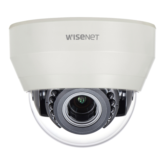
- Page 13 SCD-6085R Ω Dome Cover Shield Case Rotate base : control rotating angle of camera. Vari-focal Lens Module : 3.2 ~ 10mm (F1.6). Ω Function Setup switch : Display the menu on the screen and move the cursor to four directions to confirm status or after changing a selected item.
- Page 14 SCV-6085R Ω Dome Cover Rotate base : control rotating angle of camera. Vari-focal Lens Module : 3.2 ~ 10mm (F1.6). Function Setup switch : Display the menu on the screen and move the cursor to four Ω directions to confirm status or after changing a selected item. ƒ...
- Page 15 Ω Fixing the sunshield onto the camera. Focus lever : Set focus of lens by turn the focus lever. Ω Zoom lever : Set zoom magnification of lens by turn the zoom lever. Front cover Function Setup Switch : Display the menu on the screen and move the cursor to four directions to confirm status or after changing a selected item.
- Page 16 Back (SCO-6085R) Video signals are output through this port. Connect this port to the Video IN port of a AHD DVR. Power input terminal : Connect the power as specified for each model here.
- Page 17 1. Remove the sunshield from the camera. 2. Remove the front cover from the camera by turning it counterclockwise. 3. Unlock the Zoom or Focus lever before adjusting the lens. 4. Adjust the zoom & focus by moving the lever counterclockwise for (NEAR & WIDE) and clockwise for (TELE &...
-
Page 18: Installation
Before installing your camera, you have to adjust the lens focus, zoom, and switch settings. y When installing your camera, don’t allow any person to approach the installation site. INSTALLATION Disassembling(SCD-6085R) 1. Use one hand to hold the camera’s bottom part and turn the cover counterclockwise with another hand to separate it. - Page 19 Using the wrench provided, loosen 3 screws by turning them counterclockwise and separate the dome cover. Dome Cover...
- Page 20 1. Attach the installation template to the selected area and punch 2 holes as shown in the figure. ¾ I6³ h 2. Use the 2 supplied screws to fix the camera to the 2 punched holes. y Set the <FRONT> mark imprinted on the camera to face the direction of camera monitoring.
-
Page 21: Power Input Terminal
1. Attach the installation template on the desired surface and drill holes for screws. 2. Insert the supplied plastic anchors fully into the drilled screw holes and secure the bottom of the case (in 3 places) using the self-tapping screws. Tapping Screw 3. -
Page 22: Dome Cover
4. Adjust the lens in a desired direction by referring to the “Adjusting the monitoring direction for the camera”section. 5. Close the dome cover. To ensure waterproofing, tight up the fixing bolts using the wrench. Dome Cover The installation should be done by qualified service personnel or system installers. - Page 24 fi Adjusting the monitoring direction You can adjust the camera direction only when the camera is fixed on the ceiling. Where, rotating the camera unit to the left or right is called Pan, adjusting the tilt is called Tilt, and turning the lens on its axis is called Rotation. - The effective range of pan is a total of 350 degrees.
- Page 25 Connect the Video OUT port on the rear panel of the camera to a AHD DVR. RE C HD D ALAR M NETWOR K BACKUP POWE R AHD DVR VIDEO POWER SCD-6085R Monitor RE C HD D ALAR M NETWOR K BACKUP POWE R AHD DVR VIDEO...
-
Page 26: Connecting To Power
As the connecting method varies with the instruments, refer to the manual supplied with the instrument. y Only connect the cable when the power is turned off. CONNECTING TO POWER You can connect power as shown in the following figure. Power Input Terminal SCD-6085R... - Page 27 Power Input Terminal SCV-6085R SCO-6085R R E C Power Input Terminal When the resistance value of copper wire is at [20°C(68°F)] Copper wire size (AWG) #24 (0.22mm #22 (0.33mm #20 (0.52mm #18 (0.83mm Resistance value(Ω/m) 0.078 0.050 0.030 0.018 Voltage Drop (V/m) 0.028 0.018 0.011...
- Page 28 Coaxial Communications System y OSD Control method CAMERA MENU/ENTER UP KEY DOWN DOWN KEY LEFT LEFT KEY RIGHT RIGHT KEY RE C HD D ALAR M NETWOR K BACKUP POWE R VIDEO POWER SCD-6085R : Coaxial Cable > SCV-6085R SCO-6085R...
- Page 29 - Video Cable The camera's video output port is connected to the DVR with a BNC coaxial cable, shown below. 500m 5C2V It is recommended that pure copper coax cable is used and not copper coated steel, as this will cause issues with the communication over the coaxial cable. TO CONNECT THE MOTION DETECTION OUTPUT If devices (e.g., flashing light and siren) that exceed the voltage and current specifications are connected by using the open collector method, it may cause malfunction.
-
Page 30: Camera Operation
/ à MO T IO N RETURN EX I T / à SAV E / à NO T SAV E / à RESET MENU SETUP Use the Function Setup switch within the camera. Function Setup switch <SCD-6085R / SCV-6085R> <SCO-6085R>... -
Page 31: Video Format
MAIN SETUP X 1. VIDEO FORMAT Select the Change the status 2. PROFILE function using BASIC using the Function the Function 3. WHITE BAL Setup switch. Setup switch. 4. EXPOSURE 5. BACKLIGHT 6. SPECIAL 7. EXIT SAVE 1. Press the Function Setup switch. y Main SETUP menu is displayed on the monitor screen. - Page 32 1. When the SETUP menu screen is MAIN SETUP displayed, select ‘PROFILE’ by using 1. VIDEO FORMAT the Function Setup switch so that the X 2. PROFILE BASIC arrow indicates ‘PROFILE’ . 3. WHITE BAL 2. Select a desired mode using the 4.
-
Page 33: Main Setup
Use the White Balance function to adjust the screen color. 1. When the SETUP menu screen MAIN SETUP is displayed, select ‘White Bal’ by 1. VIDEO FORMAT using the Function Setup switch 2. PROFILE BASIC so that the arrow indicates ‘WHITE X 3. - Page 34 1. When the SETUP menu screen is displayed, select ‘EXPOSURE’ by using the Function Setup switch so that the arrow indicates ‘EXPOSURE’ . 2. Select a desired mode using the Function Setup switch. y BRIGHTNESS : Adjusts the video EXPOSURE brightness.
- Page 35 The higher the gain level, the brighter the screen - but the greater the noise. y SSNR4 : This function reduces the background noise in a low luminance environment. - OFF : Deactivates SSNR4. Noise is not reduced. - ON : Activates SSNR4 so that noise is reduced. When adjusting the noise reduction level in the SSNR4 mode, remember that the higher the level set, the more the noise level will be reduced, as will the brightness of the image.
- Page 36 The camera uses high performance DSP chips that are designed to clearly display the object and the background despite severe reverse light. 1. When the SETUP menu screen is displayed, select ‘BACKLIGHT’ by using the Function Setup switch. so that the arrow indicates ‘BACKLIGHT’ . 2.
-
Page 37: Cam Title
1. When the SETUP menu screen is displayed, select ‘SPECIAL’ by using the Function Setup switch so that the arrow indicates ‘SPECIAL’ . 2. Select a desired mode using the Function Setup switch. y DISPLAY If the SPECIAL menu screen is SPECIAL displayed, use the Function Setup X 1. -
Page 38: Image Adj
- FONT COLOR : You can change the OSD font color. (WHITE, YELLOW, GREEN, RED, BLUE) - LANGUAGE : You can select the menu language according to your requirements. - RETURN : Return to the SPECIAL menu. y COAX : You can select whether to use COAX communication. y IMAGE ADJ If the SPECIAL menu screen is displayed, use the Function Setup switch so that the arrow indicates ‘IMAGE ADJ’...
Need help?
Do you have a question about the SCD-6085R and is the answer not in the manual?
Questions and answers