Table of Contents
Advertisement
Quick Links
EN
2 1 . 0 2 – 4 4 3 8 8 3 0 _ 0 5
T r a n s l a t i o n f r o m o r i g i n a l
NXW 0500-1650
I n s t a l l a t i o n m a n u a l
60Hz
■
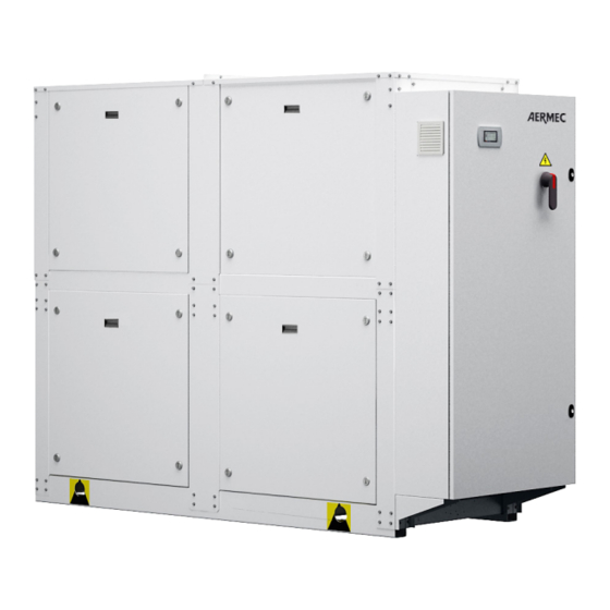
WATER-COOLED HEAT PUMP
C o o l i n g c a p a c i t y 3 1 . 5 5 ÷ 1 3 9 . 3 t o n
H e a t i n g c a p a c i t y 4 1 6 , 0 0 0 ÷ 1 , 8 1 8 , 0 0 0 B T U / h
w w w . a e r m e c . c o m
Advertisement
Table of Contents

Related Manuals for AERMEC NXW 0500-1650


Summary of Contents for AERMEC NXW 0500-1650
- Page 1 T r a n s l a t i o n f r o m o r i g i n a l NXW 0500-1650 I n s t a l l a t i o n m a n u a l 60Hz ■...
- Page 3 Dear Customer, Thank you for wanting to learn about a product Aermec. This product is the result of many years of experience and in-depth engineering research, and it is built using top quality materials and advanced technologies. The manual you are about to read is meant to present the product and help you select the unit that best meets the needs of your system.
- Page 4 All specifications are subject to change without prior notice. Although every effort has been made to ensure accuracy, Aermec shall not be held liable for any errors or omissions.
-
Page 5: Table Of Contents
TABLE OF CONTENTS General warnings .................................6 Reception ..................................8 Storage ..................................10 Dimensions - lifting points - antivibrant position mounts - position of hydraulic connections .. 11 Weight distribution and centres of gravity ...................... 20 Minimum technical spaces ............................ 24 Hydraulic connections ............................. 25 Main hydraulic circuits ............................. -
Page 6: General Warnings
An accidental release of refrigerant may cause risk of suffocation currently in force. Assess the procedures Aermec requires and due to a lack of oxygen: install the machine in a well ventilated... - Page 7 Install the unit at a distance enough from the exhaust wells, to ensure The machine and the pipes have very hot and very cold surfaces that that the possible loss of gas may reach and pollute the aquifer lead to risk of burns Keep all lubricants in properly marked containers do not keep Before opening a machine panel, ascertain whether it is or not firmly flammable liquids near the plant...
-
Page 8: Reception
CONFORMS TO ANSI UL STD 1995 CERTIFIED TO CAN/CSA STD C22.2 NO.236 the identification data of the product and by the technical plate bearing AERMEC SPA - via Roma, 996 37040 - Bevilacqua (VR) - ITALIA the performance and technical data of your unit. 3074522 comm. - Page 9 ATTENTION Use all of the available holes (Ø 65mm) for lifting The blades not included If accessory CRATE is included: Accessory Size Height Width Length CRATE_06 81.2 44.6 95.2 CRATE_07 81.2 44.6 130.7 CRATE_08 81.2 44.6 106.6 CRATE_09 81.2 44.6 144.4 CRATE_11 93.5...
-
Page 10: Storage
The anti-vibration For unit installation it is important to perform the following preliminary supports must be xed to the unit BEFORE it is earthed. AERMEC is not preparation tasks: responsible for the choice of capacity of the anti-vibration supports. -
Page 11: Dimensions - Lifting Points - Antivibrant Position Mounts - Position Of Hydraulic Connections
DIMENSIONS - LIFTING POINTS - ANTIVIBRANT POSITION MOUNTS - POSITION OF HYDRAULIC CONNECTIONS NXW_[0500-0550-0600-650-0700]_[°-X]_[°]_[L]_[°]_[T]_[6-7-8-9]_[°]_[°] 15.4 in 36.7 in 36.7 in 15.4 in 11.9 in 3.0 in 15.4 in 36.7 in 36.7 in 15.4 in 104.2 in 116.3 in 9.2 in 13.5 in 8.8 in Water connection... - Page 12 NXW_[0500-0550-0600-0650-0700]_[°-X]_[°-H]_[L]_[°]_[°]_[6-7-8-9]_[°]_[°] 12.1 in 11.8 in 46.9 in 11.8 in 11.4 in 47.7 in 11.4 in 12.1 in 70.5 in 82.7 in 13.5 in 8.9 in Water connection Heat exchanger NXW ° (Grooved joints) Condenser OUTLET 2" 1/2 US Ø Condenser INLET 2"...
- Page 13 NXW_[0500-0550-0600-0650-0700]_[°-X]_[°-H]_[L]_[°]_[°]_[6-7-8-9]_[M-N-O-P]_[U-V-W-Z] 12.0 in 15.4 in 36.7 in 36.7 in 15.4 in 15.4 in 36.7 in 36.7 in 15.4 in 116.3 in Water connection Heat exchanger NXW ° (Grooved joints) Condenser OUTLET 2" 1/2 US Ø Condenser INLET 2" 1/2 US Ø Evaporator OUTLET 2"...
- Page 14 NXW_[0750-0800]_[°-X]_[°]_[L]_[°]_[°]_[6-7-8-9]_[M-N-O-P]_[U-V-W-Z] 12.0 in 15.4 in 36.7 in 36.7 in 15.4 in 15.4 in 36.7 in 36.7 in 15.4 in 116.3 in Water connection Heat exchanger (Grooved joints) Condenser OUTLET 3" Ø Condenser INLET 3" Ø Evaporator OUTLET 2" 1/2 US Ø Evaporator INLET 2"...
- Page 15 NXW_[0750-0800-0900]_[°-X]_[°]_[L]_[°]_[T]_[6-7-8-9]_[°]_[°] 12.0 in 15.4 in 36.7 in 36.7 in 15.4 in 15.4 in 36.7 in 36.7 in 15.4 in 116.3 in Water connection Heat exchanger (Grooved joints) Condenser OUTLET 3" Ø Condenser INLET 3" Ø Evaporator INLET 2" 1/2 US Ø Evaporator OUTLET 2"...
- Page 16 NXW_[0750-0800]_[°-X]_[°]_[L]_[°]_[°]_[6-7-8-9]_[°]_[°] NXW_[0750-0800]_[°-X]_[H]_[L]_[°]_[°]_[6-7-8-9]_[°]_[°] WATER COOLED HEAT PUMP REVERSIBLE WATER SIDE 12.1 in 11.8 in 46.9 in 11.8 in 14.2 in 8.9 in Water connection Heat exchanger NXW ° (Grooved joints) Condenser OUTLET 3" Ø Condenser INLET 3" Ø Evaporator INLET 2" 1/2 US Ø Evaporator OUTLET 2"...
- Page 17 NXW_[0900]_[°-X]_[°]_[L]_[°]_[°]_[6-7-8]_[°]_[°] NXW_[0900]_[°-X]_[H]_[L]_[°]_[°]_[6-7-8]_[°]_[°] WATER COOLED HEAT PUMP REVERSIBLE WATER SIDE 11.9 in 11.8 in 59.7 in 11.8 in 31.5 in Water connection Heat exchanger NXW ° (Grooved joints) Condenser OUTLET 3" Ø Condenser INLET 3" Ø Evaporator INLET 2" 1/2 US Ø Evaporator OUTLET 2"...
- Page 18 NXW_[0900]_[°-X]_[°]_[L]_[°]_[°]_[6-7-8-9]_[M-N-O-P]_[U-V-W-Z] NXW_[0900]_[°-X]_[H]_[L]_[°]_[°]_[6-7-8-9]_[M-N-O-P]_[U-V-W-Z] 23.6 in 38.6 in 36.4 in 23.6 in 12.0 in 23.6 in 39.8 in 35.3 in 23.6 in 25.8 in 2.8in 2.8in 134.4 in 31.5 in WATER COOLED HEAT PUMP REVERSIBLE WATER SIDE REVERSIBLE WATER-COOLED HEAT PUMP, GAS SIDE 9.0 in 9.0 in 15.6 in...
- Page 19 NXW_[1000-1250-1400-1500-1650]_[°-X]_[°-H]_[L]_[°]_[°]_[7-8-]_[M-N-O-P]_[U-V-W-Z] 23.6 in 38.6 in 36.4 in 23.6 in 39.8 in 12.0 in 23.6 in 35.3 in 23.6 in 134.5 in Water connection Heat exchanger NXW ° (Grooved joints) Condenser OUTLET 3" Ø Condenser INLET 3" Ø Evaporator OUTLET 3" Ø Evaporator INLET 3"...
-
Page 20: Weight Distribution And Centres Of Gravity
WEIGHT DISTRIBUTION AND CENTRES OF GRAVITY WATER COOLED HEAT PUMP REVERSIBLE WATER SIDE Weight distribution and centres of gravity when empty Centre of mass Model Hydronic kit Empty weight (lbs) Xg (in) Yg (in) WITHOUT HYDRONIC KIT NXW 0500 L °... - Page 21 WATER COOLED HEAT PUMP REVERSIBLE WATER SIDE Weight distribution and centres of gravity when empty Centre of mass Model Hydronic kit Empty weight (lbs) Xg (in) Yg (in) WITH HYDRONIC KIT ° + 1 pump 2,027 15.2 44.1 30.4% 28.2% 21.5% 20.0% °...
- Page 22 REVERSIBLE WATER-COOLED HEAT PUMP, GAS SIDE Weight distribution and centres of gravity when empty Centre of mass Model Hydronic kit Empty weight (lbs) Xg (in) Yg (in) WITHOUT HYDRONIC KIT NXW 0500 HL ° 1,724 15.2 36.9 25.6% 23.8% 26.3% 24.3% NXW 0550 HL °...
- Page 23 REVERSIBLE WATER-COOLED HEAT PUMP, GAS SIDE Weight distribution and centres of gravity when empty Centre of mass Model Hydronic kit Empty weight (lbs) Xg (in) Yg (in) WITH HYDRONIC KIT ° + 1 pump 2,141 15.0 43.9 30.8% 27.9% 21.7% 19.7% °...
-
Page 24: Minimum Technical Spaces
MINIMUM TECHNICAL SPACES Size 0500 0550 0600 0650 0700 0750 0800 0900 1000 1250 1400 1500 1650 Minimum technical spaces 39.4 39.4 39.4 39.4 39.4 39.4 39.4 39.4 39.4 39.4 39.4 39.4 39.4 39.4 39.4 39.4 39.4 39.4 39.4 39.4 39.4 39.4 39.4... -
Page 25: Hydraulic Connections
The water circulation pump must aermec.com concentrated to ensure proper protection and prevent ice forming However, always refer to the glycol supplier documentation to check its preferably be installed upstream so that the evaporator/condenser is at minimum temperature provided for a given installation. -
Page 26: Main Hydraulic Circuits
MAIN HYDRAULIC CIRCUITS WITHOUT HYDRONIC KIT Components as standard Pressure relief valve Condenser Expansion vessel Evaporator Drain valve Water temperature sensors (IN/OUT Flow switch (MANDATORY) Components not provided and responsibility of the installer Air drain valve Water filter (MANDATORY) Storage tank Anti-vibration joints Antifreeze electric heater Flow shut-off valves... - Page 27 WITH PUMPS Single pump Single pump Single pump + stand-by pump Components as standard Air drain valve Condenser Components not provided and responsibility of the installer Evaporator Flow shut-off valves Water temperature sensors (IN/OUT) Pressure relief valve Water filter Anti-vibration joints Pump Air drain valve One-way valve...
- Page 28 WITH DESUPERHEATER Components as standard Anti-vibration joints Desuperheater Water filter (MANDATORY) Water temperature sensors (IN/OUT) Pump Components not provided and responsibility of the installer Pressure relief valve Flow shut-off valves Expansion vessel Air drain valve Drain valve WATER CHARACTERISTICS System: Chiller with plate heat exchanger 7,5 - 9 Total hardness 4,5 - 8,5 °dH...
-
Page 29: Electrical Connections
ELECTRICAL CONNECTIONS ELECTRICAL CONNECTIONS ATTENTION The units are completely wired at the factory and only require connection to the electric power supply mains, downstream from a unit switch, • All the electrical operations must be carried out by personnel in according to that envisioned by the Standards in force on this subject in the possession of the necessary quali cations by law, suitably trained and country of installation. -
Page 30: Commissioning - Warnings
COMMISSIONING - WARNINGS COMMISSIONING - WARNINGS Please note that, on request by the Aermec customer or the legitimate COMMISSIONING owner of the machine, the units in this series can be started up by Once all the aforementioned checks have been carried out, the unit... -
Page 31: Maintenance
MAINTENANCE MAINTENANCE ATTENTION place before restarting the unit; Any cleaning, inspection, control, routine and extraordinary mainte- It is not permitted to walk or place other bodies on the machine; nance must be performed by experienced, authorised personnel and Fans, motors and belt drives may be in motion, always wait for them quali ed to perform the above tasks. - Page 32 Always and only use original spare parts purchased directly from Aer- if these devices intervene, the refrigerant gas is released at high mec or from official dealers. Contact Aermec should it be necessary temperature and speed; to move the unit one year after its positioning on-site or it must be The machine and the pipes have very hot or very cold surfaces that lead to risk of burns by contact;...
- Page 33 With machine off, access its cooling circuit; The high/low pressure switch, where present must be tested with the Connect the necessary instruments, machine “closed”, reading the high pressure circuit pressure on the machine • Pressure gauges connected through appropriate extensions to the control panel.
-
Page 34: Maintenance - List Of The Recommended Periodic Interventions
MAINTENANCE - LIST OF THE RECOMMENDED PERIODIC INTERVENTIONS MAINTENANCE - LIST OF THE RECOMMENDED PERIODIC INTERVENTIONS RECOMMENDED PERIODIC MAINTENANCE INTERVENTIONS FREQUENCY DESCRIPTION functioning hours months months months months GENERAL INTERVENTIONS Check of any refrigerant leaks (this must be done respecting the deadlines recommend- •... - Page 35 MAINTENANCE - LIST OF THE RECOMMENDED PERIODIC INTERVENTIONS RECOMMENDED PERIODIC MAINTENANCE INTERVENTIONS TO UNITS WITH CENTRIFUGAL COMPRESSORS FREQUENCY DESCRIPTION 6 months 12 months other GENERAL CHECKS Check that the compressor is not damaged • Check that there are no excessive vibrations induced by other operating components •...
- Page 36 DOWNLOAD THE LATEST VERSION: http://www.aermec.com/qrcode.asp?q=5273 A E R M E C S . p . A . V i a R o m a , 9 9 6 - 3 7 0 4 0 B e v i l a c q u a ( V R ) - I t a l y P h o n e .
Need help?
Do you have a question about the NXW 0500-1650 and is the answer not in the manual?
Questions and answers