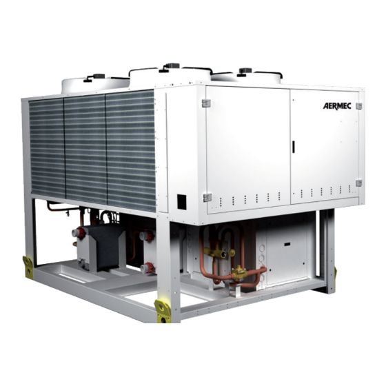
AERMEC NRP 0800 Installation Manual
Air-water multipurpose
Hide thumbs
Also See for NRP 0800:
- Technical manual (32 pages) ,
- Installation manual (44 pages) ,
- Technical installation manual (48 pages)

Related Manuals for AERMEC NRP 0800


Summary of Contents for AERMEC NRP 0800
- Page 1 T r a n s l a t i o n f r o m o r i g i n a l NRP 0800-1800 I n s t a l l a t i o n m a n u a l 60Hz ■...
- Page 3 Dear Customer, Thank you for wanting to learn about a product Aermec. This product is the result of many years of experience and in-depth engineering research, and it is built using top quality materials and advanced technologies. The manual you are about to read is meant to present the product and help you select the unit that best meets the needs of your system.
- Page 4 All specifications are subject to change without prior notice. Although every effort has been made to ensure accuracy, Aermec shall not be held liable for any errors or omissions.
-
Page 5: Table Of Contents
TABLE OF CONTENTS Sommario General warnings .................................6 Reception ..................................8 Storage .....................................9 Dimensions (mm) ..............................10 Position anti-vibration mounts ..........................11 Position of hydraulic connections ........................12 Minimum water content ............................15 Weight distribution..............................16 Minimum technical spaces ............................ 20 Basic 2-pipe system hydraulic circuits ....................... 22 Hydraulic circuit inside and outside “00”... -
Page 6: General Warnings
An accidental release of refrigerant may cause risk of suffocation currently in force. Assess the procedures Aermec requires and due to a lack of oxygen: install the machine in a well ventilated... - Page 7 Install the unit at a distance enough from the exhaust wells, to ensure The machine and the pipes have very hot and very cold surfaces that that the possible loss of gas may reach and pollute the aquifer lead to risk of burns Keep all lubricants in properly marked containers do not keep Before opening a machine panel, ascertain whether it is or not firmly flammable liquids near the plant...
-
Page 8: Reception
- Check that the equipment supplied corresponds to the order and delivery note Product identification The Aermec products can be identified by the packaging label bearing the identification data of the product and by the technical plate bearing the performance and technical data of your unit. -
Page 9: Storage
ATTENTION: The use of anti-vibration supports MUST be combined with the installation in the unit water piping of exible couplings. The anti- vibration supports must be xed to the unit BEFORE it is earthed. AERMEC is not responsible for the choice of capacity of the anti-vibration supports. -
Page 10: Dimensions (Mm)
DIMENSIONS (mm) DIMENSIONS NRP 0800 - 1000 96.5 in 2450mm 96,5in 167.5 in 4250mm 167,3in 86.7 in 2200mm 86,6in LIFTING POINTS 0800-0900 LIFTING POINTS 1000 3.9 in 3.9 in 3.9 in 3.9 in POSITION ANTI-VIBRATION MOUNTS 100mm 1825mm 1825mm 100mm... -
Page 11: Position Anti-Vibration Mounts
DIMENSIONS NRP 1250-1800 96.5 in 2450mm 96,5in 226.6 in 5750mm 226,4in 86.7 in 2200mm 86,6in LIFTING POINTS 21.7 in 43.3 in 80.8 in 43.3 in 21.7 in POSITION ANTI-VIBRATION MOUNTS 400mm 1915mm 720mm 1915mm 400mm 15,7in 75,4in 28,3in 75,4in 15,7in 15.7 in 75.4 in 28.3 in... -
Page 12: Position Of Hydraulic Connections
W REC OUT 3" W IN 3" W OUT 3" W REC IN 3" 31.5 in 75.8 in NRP 0800÷0900 | VERSION “R1-R2-R3-R4 - P1-P2-P3-P4” W REC OUT 3" W REC IN 3" W OUT 3" W IN 3" 31.5 in 71.1 in... - Page 13 NRP 1000 | VERSION “00” W IN 3" W REC OUT 3" W OUT 3" W REC IN 3" 31.5 in 75.8 in NRP 1000 | VERSION “R1-R2-R3-R4 - P1-P2-P3-P4” W REC OUT 3" W IN 3" W OUT 3" W REC IN 3"...
- Page 14 NRP 1250-1800 | VERSION “00” W IN 4" W REC OUT 4" W OUT 4" W REC IN 4" 61.1 in 105.4 in NRP 1250-1800 | VERSION “R1-R2-R3-R4 - P1-P3” W REC OUT 4" W IN 4" W REC IN 4" W OUT 4"...
-
Page 15: Minimum Water Content
DHW storage tank (measured by an SSAN probe). On the system circuit of a multifunction unit for 2-pipe systems, example 1 applies. If you are in any doubt, please refer to the relevant technical documentation or contact the Aermec Technical-Commercial Service. ATTENTION... -
Page 16: Weight Distribution
WEIGHT DISTRIBUTION NRP 0800-1000 Empty weight Integrated hydronic Integrated hydronic Xg [in] Yg [in] Weight [lb] kit, user side kit, recovery side 68.4 47.1 7,143 10.1% 12.1% 31.7% 37.7% 3.8% 4.5% R1/R3 69.5 46.4 7,452 9.5% 11.0% 32.8% 37.8% 4.2% 4.8%... - Page 17 NRP 0800-1000 Running weight Integrated hydronic Integrated hydronic Xg [in] Yg [in] Weight [lb] kit, user side kit, recovery side 68.7 46.9 7,209 10.0% 11.8% 31.9% 37.6% 3.9% 4.6% R1/R3 69.9 46.2 7,562 9.4% 10.7% 33.0% 37.7% 4.3% 4.9% R2/R4 70.8...
- Page 18 NRP 1250-1800 Empty weight Integrated hydronic Integrated hydronic Xg [in] Yg [in] Weight [lb] kit, user side kit, recovery side 93.2 48.5 9,943 10.1% 12.9% 17.7% 22.5% 13.4% 17.0% 2.8% 3.5% R1/R3 94.4 47.9 10,318 9.8% 12.1% 16.7% 20.7% 15.4% 19.1% 2.8% 3.4%...
- Page 19 NRP 1250-1800 Running weight Integrated hydronic Integrated hydronic Xg [in] Yg [in] Weight [lb] kit, user side kit, recovery side 93.7 48.3 10,097 10.0% 12.6% 17.5% 22.0% 13.9% 17.5% 2.8% 3.6% R1/R3 94.9 47.7 10,494 9.7% 11.8% 16.5% 20.1% 16.0% 19.6% 2.8% 3.4%...
-
Page 20: Minimum Technical Spaces
MINIMUM TECHNICAL SPACES NRP 0800-1000 41.6 in doors NRP 1250-1800 41.6 in doors Size 0800 0900 1000 1250 1400 1500 1650 1800 Minimum technical spaces A1 * 31.5 31.5 31.5 31.5 31.5 31.5 31.5 31.5 43.3 43.3 43.3 43.3 43.3 43.3... - Page 21 (monoethylene glycol or monopropylene glycol). Corrosion phenomena indicated in the dimension tables in this manual, or available on www. may occur with these anti-freeze solutions in contact with oxygen. aermec.com However, always refer to the glycol supplier documentation to check its recommended concentration.
-
Page 22: Basic 2-Pipe System Hydraulic Circuits
BASIC 2-PIPE SYSTEM HYDRAULIC CIRCUITS HYDRAULIC CIRCUIT INSIDE AND OUTSIDE “00” VERSION NRP Water characteristics STANDARD NRP COMPONENTS FOR 2-PIPE SYSTEMS SUPPLIED AS PER STANDARD 1 Plate heat exchanger (SYSTEM SIDE) System: Chiller with plate heat exchanger 2 Total recovery (DHW SIDE) 3 Water filter (mounted) 7.5-9 4 Flow switch (mounted) -
Page 23: Hydraulic Circuit Inside And Outside Nrp Version "With P1
HYDRAULIC CIRCUIT INSIDE AND OUTSIDE NRP VERSION “WITH P1...P4|R1...R4 PUMPS” Water characteristics STANDARD NRP COMPONENTS FOR 2-PIPE SYSTEMS SUPPLIED AS PER STANDARD 1 Plate heat exchanger (SYSTEM SIDE) System: Chiller with plate heat exchanger 2 Total recovery (DHW SIDE) 3 Water filter (supplied DHW SIDE / mounted SYSTEM SIDE) 7.5-9 4 Flow switch (mounted) Electric conductivity... -
Page 24: Basic 4-Pipe System Hydraulic Circuits
BASIC 4-PIPE SYSTEM HYDRAULIC CIRCUITS INTERNAL AND EXTERNAL HYDRAULIC CIRCUIT TO NRP “00” Water characteristics STANDARD NRP COMPONENTS FOR 4-PIPE SYSTEMS SUPPLIED AS PER STANDARD 1 Plate heat exchanger (COLD WATER PRODUCTION SYSTEM SIDE) System: Chiller with plate heat exchanger 2 Plate heat exchanger (HOT WATER PRODUCTION SYSTEM SIDE) 3 Water filter (mounted) 7.5-9... -
Page 25: Hydraulic Circuit Inside And Outside The Nrp "P1
HYDRAULIC CIRCUIT INSIDE AND OUTSIDE THE NRP “P1…P4 - R1…R4” (WITH COOLING AND HEATING SIDE PUMPS) Water characteristics STANDARD NRP COMPONENTS FOR 4-PIPE SYSTEMS SUPPLIED AS PER STANDARD 1 Plate heat exchanger (COLD WATER PRODUCTION SYSTEM SIDE) System: Chiller with plate heat exchanger 2 Plate heat exchanger (HOT WATER PRODUCTION SYSTEM SIDE) 3 Water filter (supplied DHW SIDE / mounted SYSTEM SIDE) 7.5-9... -
Page 26: Electrical Connections
ELECTRICAL CONNECTIONS ELECTRICAL CONNECTIONS ATTENTION The units are completely wired at the factory and only require connection to the electric power supply mains, downstream from a unit switch, • All the electrical operations must be carried out by personnel in according to that envisioned by the Standards in force on this subject in the possession of the necessary quali cations by law, suitably trained and country of installation. -
Page 27: Electrical Data
ELECTRICAL DATA Integrated hydronic Integrated hydronic Model 0800 0900 1000 1250 1400 1500 1650 1800 kit, user side kit, recovery side ELECTRICAL DATA: 230V-3-60HZ POWER SUPPLY 1011 1046 1115 01/02/P1/P2 1029 1064 1133 03/04/P3/P4 1036 1071 1140 R1/R2 1036 1071 1140 R3/R4 1046... - Page 28 Integrated hydronic Integrated hydronic Model 0800 0900 1000 1250 1400 1500 1650 1800 kit, user side kit, recovery side ELECTRICAL DATA: 575V-3-60HZ POWER SUPPLY 01/02/P1/P2 03/04/P3/P4 R1/R2 R3/R4 P1/P2 R1/R2 P1/P2 R3/R4 P3/P4 R1/R2 P3/P4 R3/R4 01/02/P1/P2 03/04/P3/P4 R1/R2 R3/R4 P1/P2 R1/R2 P1/P2...
-
Page 29: Electric Power Connection To The Electrical Mains
ELECTRIC POWER CONNECTION TO THE ELECTRICAL MAINS ELECTRIC POWER CONNECTION TO THE ELECTRICAL MAINS • Open the external covering panels (if present) • For the functional connection of the unit, take the power supply • Make sure that the switch is at “OFF” before opening the electric cable to the electric control board inside the unit and connect it to control board for the connection of the unit to the power supply. -
Page 30: Commissioning - Warnings
COMMISSIONING - WARNINGS COMMISSIONING - WARNINGS Please note that, on request by the Aermec customer or the legitimate COMMISSIONING owner of the machine, the units in this series can be started up by Once all the aforementioned checks have been carried out, the unit... -
Page 31: Maintenance
MAINTENANCE MAINTENANCE ATTENTION place before restarting the unit; Any cleaning, inspection, control, routine and extraordinary mainte- It is not permitted to walk or place other bodies on the machine; nance must be performed by experienced, authorised personnel and Fans, motors and belt drives may be in motion, always wait for them quali ed to perform the above tasks. - Page 32 Always and only use original spare parts purchased directly from Aer- if these devices intervene, the refrigerant gas is released at high mec or from official dealers. Contact Aermec should it be necessary temperature and speed; to move the unit one year after its positioning on-site or it must be The machine and the pipes have very hot or very cold surfaces that lead to risk of burns by contact;...
- Page 33 With machine off, access its cooling circuit; The high/low pressure switch, where present must be tested with the Connect the necessary instruments, machine “closed”, reading the high pressure circuit pressure on the machine • Pressure gauges connected through appropriate extensions to the control panel.
-
Page 34: Maintenance - List Of The Recommended Periodic Interventions
MAINTENANCE - LIST OF THE RECOMMENDED PERIODIC INTERVENTIONS MAINTENANCE - LIST OF THE RECOMMENDED PERIODIC INTERVENTIONS RECOMMENDED PERIODIC MAINTENANCE INTERVENTIONS FREQUENCY DESCRIPTION functioning hours months months months months GENERAL INTERVENTIONS Check of any refrigerant leaks (this must be done respecting the deadlines recommend- •... - Page 35 MAINTENANCE - LIST OF THE RECOMMENDED PERIODIC INTERVENTIONS RECOMMENDED PERIODIC MAINTENANCE INTERVENTIONS TO UNITS WITH CENTRIFUGAL COMPRESSORS FREQUENCY DESCRIPTION 6 months 12 months other GENERAL CHECKS Check that the compressor is not damaged • Check that there are no excessive vibrations induced by other operating components •...
- Page 36 DOWNLOAD THE LATEST VERSION: http://www.aermec.com/qrcode.asp?q=5128 A E R M E C S . p . A . V i a R o m a , 9 9 6 - 3 7 0 4 0 B e v i l a c q u a ( V R ) - I t a l y P h o n e .
Need help?
Do you have a question about the NRP 0800 and is the answer not in the manual?
Questions and answers