Advertisement
Available languages
Available languages
Quick Links
H-7058
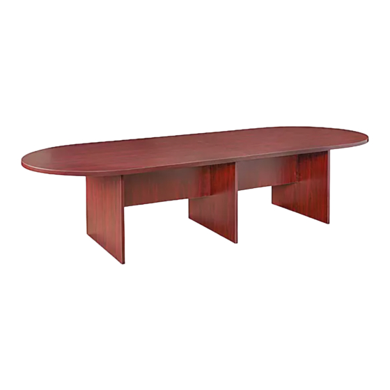
CONFERENCE TABLE
TOOLS NEEDED
Phillips
Screwdriver
(Optional)
A
Camlock Pin x 18
F
Screw x 27
M4 x 16 mm
NOTE: Assemble on a smooth, non-marring
surface to avoid scratching the table.
• Check that all parts are included.
IMPORTANT: The arrow on the camlock (B) must
point toward the camlock pin (A) for proper
alignment. Turn camlock (B) clockwise until it
locks with pin (A).
IMPORTANT: Function of Cam
Make sure the arrow is pointing upwards
before inserting into the panel's hole.
1.
Insert two camlocks (B) into holes on modesty panel
(3). Insert two camlock pins (A) and two dowels (C) in
outside leg (1). Fit outside leg (1) and modesty panel
(3) together and turn each camlock (B) clockwise
until it locks. Cover each camlock (B) with a camlock
cap (I). (See Figure 1)
PAGE 1 OF 9
1-800-295-5510
uline.com
Three Person Assembly
Drill
Required
B
Camlock x 18
G
Flat Bracket x 2
1/4 Right Turn
for Locking
PARTS
C
D
Dowel x 16
Floor Glide x 6
H
I
Deep Camlock
Camlock Cap x 13
Cap x 5
ASSEMBLY
2. Repeat to attach the second outside leg and
modesty panel together.
3. Use four camlock pins (A), four camlocks (B) and four
dowels (C) to attach center leg (2) between the two
pieces assembled in Steps 1 and 2. (See Figure 1)
A
3
B
1
Para Español, vea páginas 4-6.
Pour le français, consulter les pages 7-9.
E
L-Bracket x 4
F
Screw x 18
M5 x 19 mm
1
C
3
I
3
2
1
Figure 1
0421 IH-7058
Advertisement

Subscribe to Our Youtube Channel
Related Manuals for U-Line H-7058


Summary of Contents for U-Line H-7058
- Page 1 Para Español, vea páginas 4-6. Pour le français, consulter les pages 7-9. H-7058 1-800-295-5510 uline.com CONFERENCE TABLE TOOLS NEEDED Three Person Assembly Phillips Drill Required Screwdriver (Optional) PARTS Camlock Pin x 18 Camlock x 18 Dowel x 16 Floor Glide x 6...
- Page 2 ASSEMBLY CONTINUED 4. Place tabletop panels (4) upside down on a smooth, 6. Attach an L-Bracket (E) to each outside leg (1) and non-marring surface and push flat ends together. secure to the corresponding tabletop panel (4) Insert eight camlock pins (A) and six dowels (C). using four M4 x 16 mm screws (F) per bracket.
- Page 3 ASSEMBLY CONTINUED 8. Fasten tabletop panels (4) together by securing flat 10. With three people, turn the table over and set it bracket (G) with eight M5 x 19 mm screws (J). Tighten upright. (See Figure 7) screws with Phillips screwdriver. Repeat on the other 11.
-
Page 4: Herramientas Necesarias
H-7058 800-295-5510 uline.mx MESA DE CONFERENCIA HERRAMIENTAS NECESARIAS Se Requiere Armar Entre Desarmador Taladro Tres Personas de Cruz (Opcional) PARTES 18 Pasadores de 18 Tuercas Minifix 16 Taquetes 6 Tapas para Piso 4 Soportes en L Tuerca Minifix 27 Tornillos M4 x 16 mm... - Page 5 CONTINUACIÓN DEL ENSAMBLE 4. Coloque los paneles de la cubierta (4) boca abajo 6. Fije un Soporte en L (E) a cada pata exterior sobre una superficie lisa, que no deje marcas, para (1) y asegúrelo a la cubierta de la mesa evitar rayones.
- Page 6 CONTINUACIÓN DEL ENSAMBLE 8. Apriete juntos los paneles de la cubierta de la mesa 10. Entre tres personas, volteen la mesa y enderécenla. (4) asegurando un soporte plano (G) con ocho (Vea Diagrama 7) tornillos M5 x 19 mm (J). Apriete los tornillos con el 11.
-
Page 7: Outils Requis
H-7058 1-800-295-5510 uline.ca TABLE DE CONFÉRENCE OUTILS REQUIS Montage à trois Tournevis Perceuse personnes requis cruciforme (optionnel) PIÈCES Goujon Excentrique x 18 Cheville x 16 Patin de plancher x 6 Support en L x 4 d'excentrique x 18 Vis M4 x 16 mm x 27... - Page 8 MONTAGE SUITE 4. Placez les panneaux de la surface de table (4) 6. Fixez un support en L (E) sur chaque pied extérieur à l'envers sur une surface lisse non marquante et (1) et fixez-le au panneau de la surface de table joignez les deux côtés plats ensemble.
- Page 9 MONTAGE SUITE 8. Connectez les panneaux de la surface de table 10. Retournez la table à trois et mettez-la à l'endroit. (4) ensemble à l'aide du support plat (G) que (Voir Figure 7) vous fixerez au moyen de huit vis M5 x 19 mm (J). 11.
Need help?
Do you have a question about the H-7058 and is the answer not in the manual?
Questions and answers