Advertisement
Quick Links
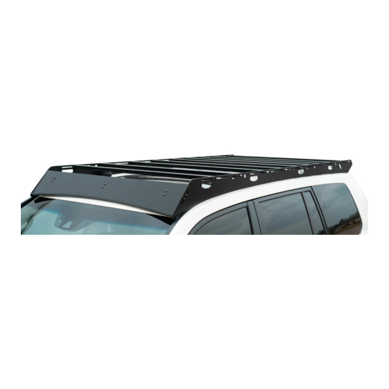
200 SE RIE S
L AN D C R UI SE R
R OOF R AC K
IN S TAL L I NSTRU C TIO NS
Please read the mounting instructions below carefully before attempting to install.
Check out the install video on the product page for factory rack disassembly.
Thank you for purchasing from Victory 4x4! Checkout our website, victory4x4.com for other great off-road
products. Be sure to rate and review our product online. If you have any questions or are missing parts, please
don't hesitate to call us at 269-459-8447!
Advertisement

Related Manuals for Victory 4x4 200 Series


Summary of Contents for Victory 4x4 200 Series
- Page 1 Check out the install video on the product page for factory rack disassembly. Thank you for purchasing from Victory 4x4! Checkout our website, victory4x4.com for other great off-road products. Be sure to rate and review our product online. If you have any questions or are missing parts, please...
-
Page 2: I Nclu D E D Hardware
I NCLU D E D HARDWARE 1/4"-20 X 3/4" 1/4"-20 X 3/8" Button Head Button Head Included with light bar cutout option. 1/4"-20 T-Nut Included with light bar cutout option. 1/4"-20 Serr. Flange Nut Washer 1/4” ID Washer 5/16” -18 X 1” Elevator Bolt 25mm M8 Button Head... -
Page 3: Included Parts
INCLUDE D PARTS 1L/1R Included with light bar cutout option. 1L/1R... - Page 4 A SS E M BLY Assemble the rack on the ground. Start by mounting the crossbars between the 2 side rails. For this, use the 1/4”-20 X 3/4” button head bolts and the 1/4” ID washers (2 per bar per side). Make sure the machined slot in the rail of the crossbar is facing up, so that you can easily add t-nuts to mount your gear.
- Page 5 A SS E M BLY Next, mount the strip of trim to the bottom edge of the front fairing. Start just to the outside of the peak of the bottom edge and continue until it reaches the equivalent point on the other side of the fairing. Cut off any extra.
- Page 6 AS SE M BLY Next, mount the front and rear fairings. To do this, use the 1/4”-20 X 3/4” button head bolts, 1/4” ID washers, and 1/4”-20 serrated flange nuts. The front fairing will need three of each per side and the rear fairing will need two of each per side.
- Page 7 ASSE M BLY Next, assemble the two halves of the front mounts. The side of the unlabeled bracket with the wider slots sits flat against the top of the of the brackets labeled with an F. It should be oriented so that the side with the smaller slots is above the flange with the letters cut out and pointing up.
- Page 8 A SS EM BLY Next, attach the mounts to inside of the rack using the 1/4”-20 X 3/4” button head bolts, 1/4” ID washers, and 1/4”-20 serrated flange nuts. The labeled flange on the mid and rear mounts should point towards the middle of the vehicle.
- Page 9 AS SE M BLY Next, apply RTV around the mounting holes on the roof of the vehicle and set the assembled rack into place. Try to get it as close to the correct position as possible so that you don’t accidentally spread the RTV while trying to sliding the rack into position.
- Page 10 A SSE MBLY With everything in place, make whatever adjustments that are necessary in order to get an even gap between the bottom edge of the rack and the roof, all the way down the length of the vehicle and then tighten it into place.
- Page 11 4 0” L IG HT B AR A S S E M B LY Slide 2 t-nuts into each of the channels on the top side of the front-most crossbar using the slots. Then, place each light bar mount over one pair of t-nuts and loosely bolt it in place using the 1/4”-20 X 3/8”...
- Page 12 D IM E NS I O N S...
Need help?
Do you have a question about the 200 Series and is the answer not in the manual?
Questions and answers