Table of Contents
Advertisement
Quick Links
Model 590 Control Valve
Operation, Parts, and Instruction Manual
TABLE OF CONTENTS
Dyna-Flo Control Valve Services Ltd.
Phone: 780
469
4000
•
•
Toll Free: 1
866
396
2356
•
•
•
2
2
2
3
4
4
5
5
5
8
8
Shaft Retainer & Retainer Screw Torque
Requirements - Table 8
8
9
10
Actuator / Valve Positions - Figure 36
11
12
12
13
14
15
Fax: 780
469
4035
•
•
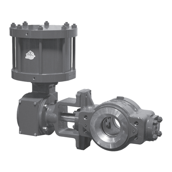
Figure 1
6 Inch 590 with DFRP-112
P-590M0817A
Website: www.dynafl o.com
17
17
17
22
22
24
25
25
28
28
28
29
30
31
32
33
40
1
Advertisement
Table of Contents

Subscribe to Our Youtube Channel
Related Manuals for Dyna-Flo 590


Summary of Contents for Dyna-Flo 590
-
Page 1: Table Of Contents
Model 590 Control Valve Operation, Parts, and Instruction Manual Figure 1 6 Inch 590 with DFRP-112 TABLE OF CONTENTS General Assembly Scope Stud Installation Safety Caution Ball and Shaft Assembly Specifi cations Ball Seal Installation Unpacking Body Outlet Installation Installation... -
Page 2: General
Operation, Parts, and Instruction Manual NOTICE These instructions are meant to be used with the Dyna-Flo 590 Technical Bulletin as they refer to Figures and Tables therein. If you do not have the Technical Bulletin, contact Dyna-Flo immediately, or visit www.dynafl... -
Page 3: Specifications
Table 1 See Parts section of manual for material listings. Contact your Model 590 Available Valve Size and ASME Rating Dyna-Flo sales offi ce for more information and other options. Valve Size Inch ASME Rating Flow Direction (See Figures 37 & 38) Single Seal Confi... -
Page 4: Unpacking
Model 590 Control Valve Operation, Parts, and Instruction Manual UNPACKING VALVE FROM SHIPPING CONTAINER Figure 2 Suggested Lifting Strap Placement Special Tools Required: • Properly Rated Lifting Straps (2 – 4 Straps) See Table 2 for valve weights. LIFTING STRAP •... -
Page 5: Air Piping
RING KEY 51 - FLANGE STUDS KEY 53 - LONG CAP SCREWS KEY 52 - SHORT CAP SCREWS Figure 3 Line Bolt Placement Example (10 Inch 590 Shown) See Figure 4 for alternative view INSTALLATION (Continued) AIR PIPING WARNING: Property damage, environmental harm, and personal injury can result from the use of supply gas other than clean, non-corrosive, oil and moisture free air. - Page 6 Model 590 Control Valve Operation, Parts, and Instruction Manual FLOW FLOW Figure 4 Valve Dimensions and Line Bolting Table 3 Model 590 Valve Dimensions - Flange Bolting - Class 600 Inch Dimensional Reference Valve Size QTY. QTY. QTY. QTY. QTY.
- Page 7 Model 590 Control Valve Operation, Parts, and Instruction Manual Table 4 Model 590 Valve Dimensions - Flange Bolting - Class 900 Inch Dimensional Reference Valve Size QTY. QTY. QTY. QTY. QTY. QTY. 4” 4.88 4.88 14.75 4.88 5.13 14.75 1-1/8 - 8 6”...
-
Page 8: Periodic Inspection
Model 590 Control Valve Operation, Parts, and Instruction Manual PERIODIC INSPECTION MAINTENANCE Special Equipment Required: Note: Shaft seals or live loaded packing and ball seals (Key 30) should all be inspected frequently for leaks, wear and • Bypass or block valves. -
Page 9: Follower Shaft
Model 590 Control Valve Operation, Parts, and Instruction Manual MAINTENANCE (Continued) Follower Shaft Seal (Outboard Seal) Reassembly (See Figure 5) SHAFT SEAL MAINTENANCE (Continued) Lubricate the backup ring (Key 8) with white petroleum Follower Shaft Seal (Outboard Seal) grease (Key C) and install into the outboard seal carrier Disassembly (See Figure 5) (Key 6). -
Page 10: Drive Shaft
Model 590 Control Valve Operation, Parts, and Instruction Manual MAINTENANCE (Continued) SHAFT SEAL MAINTENANCE (Continued) Drive Shaft Seal (Inboard Seal) Disassembly (See Figure 6) Remove the actuator (See Page 12 for Actuator Removal instructions). Remove the inboard seal carrier nuts (Key 3). -
Page 11: Ball Seal Maintenance
Model 590 Control Valve Operation, Parts, and Instruction Manual MAINTENANCE (Continued) Reassembly (See Figure 7) Note: If the ball seal (Key 30) was damaged and replaced, it BALL SEAL MAINTENANCE will be necessary to re-adjust the ball defl ection of the valve. -
Page 12: Actuator Removal
Model 590 Control Valve Operation, Parts, and Instruction Manual ACTUATOR REMOVAL DISASSEMBLY Note: Actuator removal does not require that the valve be Before You Begin: removed from the pipeline. • Read Safety Caution (Page 2). • Use safe work practices and lock out procedures. -
Page 13: Body Outlet / Seal Protector Ring
Model 590 Control Valve Operation, Parts, and Instruction Manual DISASSEMBLY (Continued) For Single Seal construction (See Figure 9) A Remove the cap screws (Key 32) from the body outlet (Key BODY OUTLET / SEAL PROTECTOR RING REMOVAL 33). (See Figure 9) B Remove the body outlet (Key 33) and body outlet gasket Remove the seal protector ring cap screws (Key 25). -
Page 14: Outboard Shaft Disassembly
Model 590 Control Valve Operation, Parts, and Instruction Manual DISASSEMBLY (Continued) Using a rubber mallet or soft block, carefully drive the follower shaft (Key 21) towards the inboard end of the OUTBOARD SHAFT DISASSEMBLY (FOLLOWER SHAFT) valve until the split ring (Key 19) can be easily accessed. -
Page 15: Inboard Shaft Disassembly
Model 590 Control Valve Operation, Parts, and Instruction Manual Figure 12 Outboard (Follower) Shaft Disassembly (Steps 4 - 6) DISASSEMBLY (Continued) OUTBOARD SHAFT DISASSEMBLY (Continued) Disassembly Steps (Continued): Remove the thrust washer (Key 13) from the follower shaft (Key 21). - Page 16 Model 590 Control Valve Operation, Parts, and Instruction Manual DISASSEMBLY (Continued) INBOARD SHAFT DISASSEMBLY (Continued) Disassembly Steps (Continued): Remove the backup ring (Key 8) from the drive shaft. Remove the seal ring (Key 9) from the drive shaft. Remove the spacer (Key 10) from the drive shaft.
-
Page 17: Assembly
Model 590 Control Valve Operation, Parts, and Instruction Manual ASSEMBLY Before You Begin: • Read Safety Caution (Page 2). • Use safe work practices and lock out procedures. • Clean and inspect all parts. • Replace or repair damaged parts. Replace all soft parts (Seals, o-rings, gaskets, live loaded packing). - Page 18 Model 590 Control Valve Operation, Parts, and Instruction Manual ASSEMBLY (Continued) BALL AND SHAFT ASSEMBLY (Continued) Place the valve body (outlet side up) onto blocks (see Figure 19 for block placement) on a fl at work surface that can support the full assembled valve weight.
- Page 19 Model 590 Control Valve Operation, Parts, and Instruction Manual OUTLET SIDE INLET SIDE BLOCK BLOCK BLOCK BLOCK Figure 19 Support Block Placement (Step 6) SEE NOTE Align Index Marks NOTE: For rare circumstances when the alignment mark is not visible (on the 10 inch ball for example), move the ball into the fully open position inside the valve body and insert the tapered polygon end connection of the shaft into the ball so that the alignment mark of the shaft polygon is placed into the corner of the ball polygon that faces the open end of the valve ball (parallel to the fl...
- Page 20 Model 590 Control Valve Operation, Parts, and Instruction Manual OUTBOARD (FOLLOWER) SHAFT ASSEMBLY (SEE FIGURE 16) Figure 22 Outboard (Follower) Shaft Installation (Steps 14 - 15) ASSEMBLY (Continued) thread on the nuts (Key 3). Note: See Figure 5 for locator pin (Key 22) alignment. Tighten the seal carrier BALL AND SHAFT ASSEMBLY (Continued) nuts completely but DO NOT TORQUE them into place.
- Page 21 Model 590 Control Valve Operation, Parts, and Instruction Manual SEE FIGURE 18 Figure 24 Shaft Seal Installation Diagram (Step 18 - 29) ASSEMBLY (Continued) 24 Install 6 shims (Key 11) into the inboard (drive) shaft bore. Temporarily install the spacer (Key 10). Install the backup...
-
Page 22: Ball Seal Installation
Model 590 Control Valve Operation, Parts, and Instruction Manual ASSEMBLY (Continued) Apply silicone-based o-ring compound (Key B) to the seal protector o-ring (Key 29). Lay the o-ring into the valve BALL AND SHAFT ASSEMBLY (Continued) body (Key 1) so that it rests on top of the shims (Key 31). - Page 23 Model 590 Control Valve Operation, Parts, and Instruction Manual Figure 26 Typical Single Seal Valve Disassembly Figure 27 Typical Dual Seal Valve Disassembly AFTER 3 SHIMS (KEY 31) HAVE BEEN REMOVED Figure 28 Proper Ball Seal and Shim Installation (Step 16) P-590M0817A Dyna-Flo Control Valve Services Ltd.
-
Page 24: Flow Ring Installation
Model 590 Control Valve Operation, Parts, and Instruction Manual BALL AND FLOW RING CLEARANCE ASSEMBLY (Continued) FLOW RING INSTALLATION Before You Begin: • Read Safety Caution (Page 2). • Use safe work practices and lock out procedures. • Clean and inspect all parts. -
Page 25: Live Loaded Packing
Model 590 Control Valve Operation, Parts, and Instruction Manual LIVE LOADED PACKING Apply silicone-based o-ring compound (Key B) to the seal carrier o-ring (Key 7). Install the o-ring. DISASSEMBLY Before You Begin: Install the live loaded packing box (Key 49). - Page 26 Model 590 Control Valve Operation, Parts, and Instruction Manual Figure 31 6 Inch Valve Inboard and Outboard Live Loaded Packing Arrangement Figure 32 4 & 8 Inch Valve Inboard and Outboard Live Loaded Packing Arrangement P-590M0817A Dyna-Flo Control Valve Services Ltd.
- Page 27 Model 590 Control Valve Operation, Parts, and Instruction Manual Figure 33 10 Inch Valve Inboard and Outboard Live Loaded Packing Arrangement Figure 34 12 Inch Valve Inboard and Outboard Live Loaded Packing Arrangement P-590M0817A Dyna-Flo Control Valve Services Ltd. Phone: 780...
-
Page 28: Travel Adjustment
Model 590 Control Valve Operation, Parts, and Instruction Manual TRAVEL ADJUSTMENT For Assemblies Removed From Pipeline: Rotate the ball (Key 2) to the fully open position. The ball is Adjustments can be made to actuator travel with the valve assembly either in or removed from the pipeline. -
Page 29: Ball Support Post And Retainer Removal Tool
Model 590 Control Valve Operation, Parts, and Instruction Manual Z1/Z2 Figure 35 Ball Support Post and Shaft Retainer Removal Tool Construction Dimensions Table 9 Ball Support Post and Shaft Retainer Removal Tool Dimensions Inch (mm) Valve Size 1.615 1.245 0.342 (41.02) - Page 30 Model 590 Control Valve Operation, Parts, and Instruction Manual Figure 36 Actuator / Valve Position Chart ACTUATOR VALVE OPEN (diagrams shown using DFRP model actuators) STYLE A PUSH DOWN TO CLOSE CLOSE (PDTC) FLOW ACTUATOR POSITIONS CLOSE STYLE B PUSH DOWN TO OPEN...
- Page 31 Model 590 Control Valve Operation, Parts, and Instruction Manual INBOARD SIDE Figure 37 Typical Single Seal Valve Assembly INLET FRONT VIEW 24 23 OUTBOARD SIDE P-590M0817A Dyna-Flo Control Valve Services Ltd. Phone: 780 4000 Toll Free: 1 2356 Fax: 780 4035 Website: www.dynafl...
- Page 32 Model 590 Control Valve Operation, Parts, and Instruction Manual INBOARD SIDE Figure 38 Typical Dual Seal Valve Assembly INLET FRONT VIEW 24 23 OUTBOARD SIDE P-590M0817A Dyna-Flo Control Valve Services Ltd. Phone: 780 4000 Toll Free: 1 2356 Fax: 780 4035 Website: www.dynafl...
-
Page 33: Parts
Model 590 Control Valve Operation, Parts, and Instruction Manual Parts Description Part Number Description Part Number Outboard Seal Carrier, S31600 4 Inch 28A2514X03D Body 6 Inch 38A2539X03D if you need a body as a replacement part, order by 8 Inch... - Page 34 Model 590 Control Valve Operation, Parts, and Instruction Manual Parts (Continued) Description Part Number Drive Shaft, Continued Description Part Number 12 Inch 38A2636X02D Bushing, S31600/S31603 Dual Grade / CPTFE, 16 Inch 38A8604X02D 2 Required Pin, Follower Shaft, 4 Inch 18A2520X04D...
- Page 35 Model 590 Control Valve Operation, Parts, and Instruction Manual Parts (Continued) Description Part Number Seal Protector Ring, Dual Seal (Continued) Description Part Number -WCC (Special Order) Indicator Scale, Continued 4 Inch 38A2508X04A 12 Inch 38A5034X01D 6 Inch 38A2533X04A 16 Inch...
- Page 36 Model 590 Control Valve Operation, Parts, and Instruction Manual Parts (Continued) Description Part Number Body Outlet Description Part Number 10 Inch 31B9719X02A Ball Seal, Acetal 12 Inch 32B0033X02A 4 Inch 18A2528X01D 16 Inch 48A4592X02A 6 Inch 18A2553X01D Gasket, Body Outlet / Adapter Ring,...
-
Page 37: Single Seal Cross Section - Figure
12 Inch LLR30590PFD Whenever corresponding with Dyna-Flo 16 Inch about a 590 Control Valve, refer to the nameplate for the serial number of the 42-48 See Table 10 unit. Please order by the complete part number (as given in the following parts list) of each part required. -
Page 38: Dual Seal Cross Section - Figure
Model 590 Control Valve Operation, Parts, and Instruction Manual Table 10 Live Loaded Packing Retro-Fit Kit Valve Size Part Number 4 Inch R590XLR040D 6 Inch R590XLR060D 8 Inch R590XLR080D 10 Inch R590XLR100D 12 Inch R590XLR120D 16 Inch R590XLR160D Kit Includes... - Page 39 Model 590 Control Valve Operation, Parts, and Instruction Manual This page left intentionally blank. P-590M0817A Dyna-Flo Control Valve Services Ltd. Phone: 780 4000 Toll Free: 1 2356 Fax: 780 4035 Website: www.dynafl o.com • • • • • • •...
-
Page 40: Model Builder
Model 590 Control Valve MODEL NUMBERING SYSTEM S A M P L E PA R T N U M B E R : 590- 8 - C L S - P N VALVE SIZE 4 INCH 6 INCH 8 INCH...
Need help?
Do you have a question about the 590 and is the answer not in the manual?
Questions and answers