Advertisement
Quick Links
Instruction Manual October 2005
Dyna-Flo 4000
Operation, Parts and Instruction Manual
Table of Contents
Output Signal
Start-Up & Tuning
Parts
Kits
Detailed
Dyna-Flo Control Valve Services Ltd.
Edmonton, Alberta, CANADA
Website: www.dynaflo.com
M ode l
400 0
Co ntr ol Valve
O pe rat i o n , Par ts an d I n st ru c ti o n M anu al s
2
4
5
6
8
9
11
12
12
15
Toll Free: 1
•
Fax: 780
469
4000
•
•
866
396
2356
•
•
469
3149
•
•
1
Advertisement

Summary of Contents for Dyna-Flo 4000
-
Page 1: Table Of Contents
Table of Contents Calibration Adjustments Maintenance Changing Action Relay Manifold Output Signal Start-Up & Tuning Parts Kits Detailed Dyna-Flo Control Valve Services Ltd. Phone: 780 4000 • • Toll Free: 1 2356 Edmonton, Alberta, CANADA • • • Fax: 780 3149 •... - Page 2 O pe rat i o n , Par t s a nd I ns tr u ct io n M anu al s !NOTICE! These instructions are meant to be used with the Dyna-Flo 4000 Series Technical Bulletin as they refer to Figures and Tables therein. If you do not have the Technical Bulletin, contact Dyna-Flo immediately, or visit www.dynaflo.com...
-
Page 3: Calibration
If the 4010 is to be left at the maximum Reset value is bourdon tube uper limit.) setting, the 4010 controller will perform as a 4000 (porportional band) controller. It is Isolate the controller from process, control, and recommended taht the reset bellows tubing be supply pressure. -
Page 4: Adjustments
Calibration Procedure Adjustments Initial Set-up (cont’d) Manual Set Point (4000 / 4010 / 4020) 4020 Controller (cont’d) Adjust the pressure setting by turning the pressure Calibrate as a 4000 (proportional band) setting knob (Figure 4) to the desired pressure. This represents the upper switch point for a direct acting controller. -
Page 5: Maintenance
Remove the machine screws and washer process connections. (Key 19 and 72) and dial (Key 20). Dyna-Flo Control Valve Services Ltd. Phone: 780 4000 • • Toll Free: 1... -
Page 6: Changing Action
Disconnect the tubing and remove the reset restriction valve assembly (Figure 6) by removing a retaining screw (not shown) on the For a 4000 (proportional-only) controller back of the controller. Disconnect the proportional tubing (Key 10) from the bellows frame and reconnect it in the opposite hole. - Page 7 R = R ES ET B EL L O W S X = N O PR ESSU R E Direct Acting Reverse Acting MODEL 4000 Proportional-Plus Reset Controller Figure 2 Tubing Connections For both Models of Controllers (cont’d) Install the sealing screw with o-ring in the...
-
Page 8: Relay Manifold
76) bottom diaphragm (Key 86), spacer ring (Key 84), diaphragm assembly (Key 75), relay spring (Key 82), and valve plug spring (Key 88) from the relay manifold (Key 81). Dyna-Flo Control Valve Services Ltd. Phone: 780 4000 • •... - Page 9 With the manifold in 63, Figure 2), at the relay end. place, insert and fasten the 2 screws (Key 39 not shown) from the backside of the case. Dyna-Flo Control Valve Services Ltd. Phone: 780 4000 •...
- Page 10 Use Proper Thread Sealant on all tubing assembly. connections. Remove the bellows connecting stud (not shown) for re-use with the new bellows. Dyna-Flo Control Valve Services Ltd. Phone: 780 4000 • • Toll Free: 1...
- Page 11 Check the reset setting for stable operation by watching for cycling. making a change in the process and watching for cycling. Dyna-Flo Control Valve Services Ltd. Phone: 780 4000 • •...
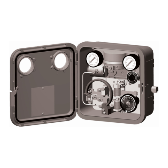
- Page 12 P r essur e Cont r oll er O pe rat i o n , Par t s a nd I ns tr u ct io n M anu al s Figure 4 Dyna-Flo Model 4000 General Detail Parts Ordering...
- Page 13 (not shown) 0-600 psig 16A7662X06D Nameplate Screw, 1C94192898D steel pl 0-1000 psig 16A7662X07D (2 req’d) 0-1500 psig 16A7662X08D Dyna-Flo Control Valve Services Ltd. Phone: 780 4000 • • Toll Free: 1 2356 Edmonton, Alberta, CANADA • • • Fax: 780 3149 •...
- Page 14 Mounting Bracket, actuator 1C22182502D Sleeve, Delrin 16A0976X01D yoke, steel pl (not shown) Spacer, 1H26594401D aluminum -Dyna-Flo Model DFC, DFR, and Others Spring Washer, PC00000004D steel pl Mounting Bracket, 1H2892000AD Vent Assembly, Y602-12D plastic/sst Panel or Wall, steel pl (2 req’d)
- Page 15 Figure 6 4010 Controller General Arrangement Reset Valve Assembly Proportional Band Tubing (To Reset Valve) Proportional Band Tubing Reset Tubing Not Shown: Reset Valve Mounting Screw Dyna-Flo Control Valve Services Ltd. Phone: 780 4000 • • Toll Free: 1 2356 Edmonton, Alberta, CANADA •...
- Page 16 P r essur e Cont r oll er O pe rat i o n , Par t s a nd I ns tr u ct io n M anu al s Figure 12 Model 4000 Mounting Details, Pipestand, Surface Panel Dyna-Flo Control Valve Services Ltd.
- Page 17 Mounting Details, Actuator Yoke Our Commitment of Quality Dyna-Flo is committed to continuous improvement. All efforts have been taken to maximize the accuracy of this information.Without notification, product specifications and designs may be modified at any time. The issue of this document is forinformation only, and does not imply suitability, a warranty, or guarantee for a specific service.


Need help?
Do you have a question about the 4000 and is the answer not in the manual?
Questions and answers