Table of Contents
Advertisement
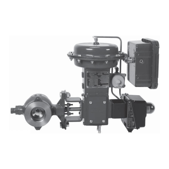
Model 570, 571, 573 Control Valve
Operation, Parts, and Instruction Manual
TABLE OF CONTENTS
Valve Assembly / Dimensions - Figure 2
Mounting - Figures 5 / 6
Dyna-Flo Control Valve Services Ltd.
Phone: 780
469
4000
•
•
Toll Free: 1
866
396
2356
•
•
•
2
2
3
5
6
4
7-8
5
6
6
7
7
9
10
13
570 / 571 / 573 Cross Sections - Figures 71-75
11
12
Fax: 780
469
4035
•
•
P-570M0919A
Website: www.dynafl o.com
13
14
15
15
16
18
23
25
26
26
27
35
40
46
48-51
52
60
1
Advertisement
Table of Contents

Subscribe to Our Youtube Channel
Related Manuals for Dyna-Flo 570


Summary of Contents for Dyna-Flo 570
-
Page 1: Table Of Contents
Ball Seal Installation Installation / Actuator Mounting 3 to 12 Inch Ball / Shaft Connection Periodic Inspection 570 / 571 / 573 Cross Sections - Figures 71-75 48-51 Mounting - Figures 5 / 6 Parts Mounting Styles and Positions - Table 14... -
Page 2: General
Operation, Parts, and Instruction Manual NOTICE These instructions are meant to be used with the Dyna-Flo 570 Series Technical Bulletin as they refer to Figures and Tables therein. If you do not have the Technical Bulletin, contact Dyna-Flo immediately, or visit www.dynafl o.com Each control valve is factory checked. -
Page 3: Specifi Cations
Refer to Table 16 of the Sales Bulletin for construction - Splined (Standard) materials. - Square (Optional - 1” to 6” Valves) Contact your Dyna-Flo sales offi ce for more information and - Keyed (Optional - 8” to 16” Valves) other options. Flow Direction For more information and other options contact your Dyna-Flo Forward (through seal into ball). -
Page 4: Flange Stud Lengths - Table
Model 570, 571, 573 Control Valve Operation, Parts, and Instruction Manual Table 1 Available Valve Confi gurations Valve Size Valve Model End Connection Body Material Valve Rating inch 1 / 1-1/2 / 2 ASME Class 150/300/600 Flangeless ASME Class 150 Mates with ASME Class 3 &... -
Page 5: 573 Flange Stud Lengths - Table
Model 570, 571, 573 Control Valve Operation, Parts, and Instruction Manual MODEL 570 MODEL 571 & 573 SPLINED SHAFT 3” TO 16” VALVES 1 - 2” VALVE Centering Studs 8” - 16” VALVE KEYED SHAFT DETAIL (SQUARE) 1” - 6” VALVES... -
Page 6: Flange Stud Diameters - Table
Figure 3 Flange Stud Measuring Method MEASURE FROM FIRST FULL THREAD TO FIRST FULL THREAD Table 4 Model 570 Line Flange Stud Lengths Inch (mm) - Refer to Figure 2. Valve Size (inches) Class 150 Class 300 Class 600 6.94 (176) 7.94 (202) -
Page 7: Flange Stud Quantity - Table
10 (571 & 573 ONLY) 12 (571 & 573 ONLY) 16 (571 & 573 ONLY) Table 8 Model 570 Valve Mounting Pad Dimensions Inch (mm) - Refer to Figure 2. Dimensional Reference Valve Size Inch 1 / 1-1/2 / 2 0.56 (14.2) -
Page 8: Mounting Pad Dimensions - Tables 8
1-1/2 (38.1) 16 (571) 2-1/8 x 2 (54.0 x 50.8) 16 (573) 2-1/8 (54.0) Table 11 Model 570, 571, and 573 Splined Shaft Dimensions Inch (mm) - Refer to Figure 2. Valve Size Inch 7.38 (188) 1/2 (12.7) 7.38 (188) 7.38 (188) -
Page 9: Unpacking
Model 570, 571, 573 Control Valve Operation, Parts, and Instruction Manual Table 12 Model 570, 571, and 573 Keyed Shaft Dimensions Inch (mm) - Refer to Figure 2. 571 & 573 Valve Size Inch 5.05 1-1/4 1.50 1-1/8 1.63 5.05 1-1/4 1.50... -
Page 10: Installation / Actuator Mounting
Proceed to Air Piping (Page 12). and 3, and Tables 4 to 7 for stud size and quantity. The Model 570 is designed to utilize long studs to assist in centering the valve in-line. Models 571 and 573 use shorter studs to Models 571 &... - Page 11 Model 570, 571, 573 Control Valve Operation, Parts, and Instruction Manual Left Hand Mount Figure 5 Mounting Orientation Diagram Figure 6 Actuator/Valve Position Chart Right Hand Mount ACTUATOR VALVE OPEN (diagrams shown using DFR model actuators) STYLE A CLOSE PUSH DOWN TO CLOSE...
- Page 12 Model 570, 571, 573 Control Valve Operation, Parts, and Instruction Manual Table 14 Mounting Styles and Positions Position Mounting Action (Refer to Figures 5 & 6) Right Hand Mount Fail Open Style A Right Hand Mount Fail Close Style B...
-
Page 13: Periodic Inspection
Model 570, 571, 573 Control Valve Operation, Parts, and Instruction Manual PERIODIC INSPECTION MAINTENANCE Special Equipment Required: NOTE: Packing and ball seals (Key 26) should all be inspected frequently for leaks, wear and damage. Maintenance to the • Bypass or block valves. -
Page 14: Mounting Styles And Positions - Table
Model 570, 571, 573 Control Valve Operation, Parts, and Instruction Manual MAINTENANCE (Continued) ACTUATOR REMOVAL BALL SEAL MAINTENANCE (Continued) Note: Actuator removal does not require that the valve be removed from the pipeline. In some circumstances it may be Maintenance for ball seals consists mainly of seal replacement. -
Page 15: Disassembly
Model 570, 571, 573 Control Valve Operation, Parts, and Instruction Manual DISASSEMBLY Before You Begin: • Read Safety Caution (Page 2). • Use safe work practices and lock out procedures. • Remove the actuator from the valve. Use caution, even with the actuator removed the valve ball can still rotate. -
Page 16: Ball Seal Removal
• Place the valve in to the OPEN position. For 1 to 8 Inch 570 Valves (Refer to Figures 10 & 11): FOR 1 - 12 INCH 571/573 VALVES Remove the seal protector screws (Key 35) and seal protector clips (Key 33). - Page 17 Model 570, 571, 573 Control Valve Operation, Parts, and Instruction Manual Figure 12 Backup Ring Removal Figure 11 Seal Protector Ring / Flow Ring Removal DISASSEMBLY (Continued) BALL SEAL REMOVAL (Continued) For 1 to 2 Inch Valves (Refer to Figure 12): Remove the back up ring (Key 25) if present.
-
Page 18: Ball And Shaft Removal
Model 570, 571, 573 Control Valve Operation, Parts, and Instruction Manual OUTLET DISASSEMBLY (Continued) BALL AND SHAFT REMOVAL Before You Begin: • Read Safety Caution (Page 2). • Use safe work practices and lock out procedures. • Be aware of potentially hazardous process material that may... - Page 19 Model 570, 571, 573 Control Valve Operation, Parts, and Instruction Manual Figure 16 Follower Shaft and Ball Removal (Steps 6 to 10) for 2 Inch Valves DISASSEMBLY (Continued) BALL AND SHAFT REMOVAL (Continued) or 1 to 2 Inch Valve Shaft Removal (Continued): Support the ball (Key 6) and push the follower shaft (Key 9) towards the center of the ball.
- Page 20 Model 570, 571, 573 Control Valve Operation, Parts, and Instruction Manual PUNCH DISASSEMBLY (Continued) BALL AND SHAFT REMOVAL (Continued) For 3 to 12 Inch Valve Shaft Removal: NOTE: 3 to 12 inch valves use a combination of shaft key (Key 12) and pin (Key 10) to connect the shafts (Key 9 &...
- Page 21 Model 570, 571, 573 Control Valve Operation, Parts, and Instruction Manual DISASSEMBLY (Continued) BALL AND SHAFT REMOVAL (Continued) For 3 to 12 Inch Valve Shaft Removal (Continued): Remove the drive shaft (Key 11) from the actuator side of the valve. Refer to Figure 19.
- Page 22 Model 570, 571, 573 Control Valve Operation, Parts, and Instruction Manual Figure 22 16 Inch Flange / Spiral Wound Gasket / Bearing Removal Figure 23 16 Inch Shaft Retainer Removal Figure 24 16 Inch Follower Shaft Removal DISASSEMBLY (Continued) PUNCH...
-
Page 23: Bearing Removal
• Be aware of potentially hazardous process material that may be present in-valve. NOTE: If the bearings (Key 3) need to be replaced, be aware that Dyna-Flo bearing confi gurations have changed for 570 series control valves. New replacement bearing kits will refl ect this change:... - Page 24 Model 570, 571, 573 Control Valve Operation, Parts, and Instruction Manual DISASSEMBLY (Continued) Pull or drive the inboard bearing (Key 3) towards the center of the valve body (Key 1) and remove it. Refer to BEARING REMOVAL (Continued) Figure 29C.
-
Page 25: Bearing Driver Construction Dimensions
Model 570, 571, 573 Control Valve Operation, Parts, and Instruction Manual PUSH PUSH Figure 29B 3 to 12 Inch Outboard Bearing Removal Figure 29C 3 to 16 Inch Inboard Bearing Removal WATER BEADING THRUST WASHER WATER TEST Thrust washers (Key 7) should only need to be removed and replaced if there is wear or damage, otherwise they can be left attached to the bearing (Key 3) during maintenance. -
Page 26: Assembly
® BEARING INSTALLATION NOTE: If the bearings (Key 3) need to be replaced, be aware that Dyna-Flo bearing confi gurations have changed for 570 series control valves. New replacement bearing kits will refl ect this change: Inboard and outboard bearings are only present for valve sizes 6”... -
Page 27: Ball / Shaft Installation
Model 570, 571, 573 Control Valve Operation, Parts, and Instruction Manual ASSEMBLY (Continued) BEARING INSTALLATION (Continued) For 1 to 12 Inch Valves: Apply Permatex Nickel Anti-Seize or equivalent (Key A) to ® the outside surface of the bearings (Key 3). Refer to Figure 35. - Page 28 Model 570, 571, 573 Control Valve Operation, Parts, and Instruction Manual ASSEMBLY (Continued) BALL / SHAFT INSTALLATION (Continued) For Old Style 1 to 1-1/2 Inch Valves (Continued): Insert the ball/follower shaft assembly (Keys 6 & 9) in to the valve body (Key 1) and position the ball so that the follower shaft can be pushed in to the outboard bore of the valve body.
- Page 29 Model 570, 571, 573 Control Valve Operation, Parts, and Instruction Manual STAKE Figure 40 1 to 2 Inch Shaft Connection Pin Stake Locations (2 inch valve stake locations are 180 apart) ASSEMBLY (Continued) BALL / SHAFT INSTALLATION (Continued) For 1 to 12 Inch Valves:...
- Page 30 Model 570, 571, 573 Control Valve Operation, Parts, and Instruction Manual Figure 44 2 to 12 Inch Valve Ball Installation Figure 42 Thrust Washer Installation Figure 43 2, 3, 4, 10 & 12 Inch Follower Shaft Installation ASSEMBLY (Continued) BALL / SHAFT INSTALLATION (Continued)
- Page 31 Model 570, 571, 573 Control Valve Operation, Parts, and Instruction Manual Figure 46 2, 3, 4, 10 & 12 Inch Follower Pin Installation ASSEMBLY (Continued) Figure 48 3 to 12 Inch Shaft Key Installation BALL / SHAFT INSTALLATION (Continued) For 1 to 12 Inch Valves (Continued):...
- Page 32 Model 570, 571, 573 Control Valve Operation, Parts, and Instruction Manual ASSEMBLY (Continued) BALL / SHAFT INSTALLATION (Continued) For 16 Inch Valves: Apply LOCTITE 495 Instant Adhesive or equivalent (Key D) ® to the back side of the thrust washer (Key 7) if applicable.
- Page 33 Model 570, 571, 573 Control Valve Operation, Parts, and Instruction Manual Figure 52 16 Inch Drive Shaft Pins Installation Figure 53 16 Inch Follower Shaft Pin Installation ASSEMBLY (Continued) 10 Apply Permatex® Nickel Anti-Seize or equivalent (Key A) to the threads of the fl ange studs (Key 2) and thread the BALL / SHAFT INSTALLATION (Continued) nuts (Key 24) on to the studs hand tight.
- Page 34 Model 570, 571, 573 Control Valve Operation, Parts, and Instruction Manual Figure 54 16 Inch Shaft Retainer Installation ASSEMBLY (Continued) BALL / SHAFT INSTALLATION (Continued) For 16 Inch Valves (Continued): 12 Torque the shaft retainers (Key 15) to 90 lbf-ft. (122 N m).
-
Page 35: Packing Installation
Model 570, 571, 573 Control Valve Operation, Parts, and Instruction Manual ASSEMBLY (Continued) PACKING INSTALLATION Refer to Before You Begin section on Page 26 before proceeding with packing installation. Lubricants Required: • Permatex Nickel Anti-Seize or equivalent (Key A) ®... - Page 36 Model 570, 571, 573 Control Valve Operation, Parts, and Instruction Manual ASSEMBLY (Continued) PACKING INSTALLATION (Continued) For Standard Graphite Packing: Slide the packing box ring (Key 16) over the valve shaft (Key 11) and down into the packing bore. Use the packing...
- Page 37 Model 570, 571, 573 Control Valve Operation, Parts, and Instruction Manual ASSEMBLY (Continued) Install the graphite packing rings (Keys 17A & 18) one ring at a time (as described in the NOTE on Page 35) in the PACKING INSTALLATION (Continued) proper order and orientation as shown in Figure 60.
- Page 38 Model 570, 571, 573 Control Valve Operation, Parts, and Instruction Manual LIVE LOADED PTFE V-RING LIVE LOADED GRAPHITE PACKING PACKING Figure 60 Packing Confi guration Diagrams (Refer to Figure 61 & 62 for Spring Washer, Key 21, Arrangements) P-570M0919A Dyna-Flo Control Valve Services Ltd.
- Page 39 Model 570, 571, 573 Control Valve Operation, Parts, and Instruction Manual PTFE ARRANGEMENT PTFE ARRANGEMENT PTFE ARRANGEMENT FOR 1/2” & 5/8” SHAFTS FOR 3/4” & 1” SHAFTS FOR 1-1/4” & 1-1/2” SHAFTS Figure 61 Live Loaded PTFE Spring Washer (Key 21) Arrangements...
-
Page 40: Ball Seal Installation
NOTE: The following instructions assume that the actuator was removed from the valve assembly. It is not however a For 1 to 8 Inch 570 Valves (Refer to Figure 65): requirement to have the actuator removed from the valve in Install the seal protector clips (Key 33) and thread the order to service the ball seal. - Page 41 Model 570, 571, 573 Control Valve Operation, Parts, and Instruction Manual FOR 1 - 8 INCH 570 VALVES FOR 1 - 12 INCH 571/573 VALVES Figure 63 1 to 2 Inch Ball Seal Installation FOR 16 INCH VALVES LIFTING HOLE...
- Page 42 Model 570, 571, 573 Control Valve Operation, Parts, and Instruction Manual CLEARANCE ANGLES Figure 66 Diagram - Clearance Angles for Ball Centering ASSEMBLY (Continued) Carefully install the metal ball seal (Key 27) in to the seal protector ring (Key 31). The metal ball seal must be...
- Page 43 Model 570, 571, 573 Control Valve Operation, Parts, and Instruction Manual ASSEMBLY (Continued) BALL SEAL INSTALLATION (Continued) Metal Ball Seals (Continued) For 16 Inch Valves (Refer to Figure 65): Make sure the cap screw holes of the seal protector ring (Key 31) are aligned with the holes in the valve body (Key 1).
- Page 44 Model 570, 571, 573 Control Valve Operation, Parts, and Instruction Manual ASSEMBLY (Continued) Manually stroke the valve if possible and observe that the valve operates smoothly. BALL SEAL INSTALLATION (Continued) Flow Rings Rotate the ball (Key 6) to the closed position.
- Page 45 Model 570, 571, 573 Control Valve Operation, Parts, and Instruction Manual Figure 70 Ball Seal Assembly Diagrams for Valve Sizes 1 Through 16 Inch VALVE BODY SEAL PROTECTOR (Key 1) VALVE BODY (Key 1) (Key 31) RING SEAL PROTECTOR (Key 31)
-
Page 46: To 12 Inch Ball / Shaft Connection
Model 570, 571, 573 Control Valve Operation, Parts, and Instruction Manual 3 THROUGH 12 INCH BALL TO SHAFT ASSEMBLY INSTRUCTIONS These instructions outline the recommended procedure for assembly and setting of the ball (Key 6) to shaft (Key 11) connection. - Page 47 Model 570, 571, 573 Control Valve Operation, Parts, and Instruction Manual After the setscrew(s) (Key 14) are tight, fl ip the ball/shaft assembly in the vise as shown. Using a punch, remove the shaft key (Key 12) from the ball/shaft (Keys 6 & 11) connection and then separate the ball from the shaft.
- Page 48 Model 570, 571, 573 Control Valve Operation, Parts, and Instruction Manual ROTATED 90 FOR CLARITY Figure 71 1 & 1-1/2 Inch Model 570 Cross Section ROTATED 90 FOR CLARITY Figure 72 2 Inch Model 570 Cross Section P-570M0919A Dyna-Flo Control Valve Services Ltd.
- Page 49 ROTATED 90 FOR CLARITY *NOTE: 3 AND 4 INCH VALVES DO NOT HAVE A THRUST WASHER (KEY 7). Figure 73 3 to 8 Inch Model 570 Cross Section P-570M0919A Dyna-Flo Control Valve Services Ltd. Phone: 780 4000 Toll Free: 1...
- Page 50 Model 570, 571, 573 Control Valve Operation, Parts, and Instruction Manual ROTATED 90 FOR CLARITY *NOTE: 3 AND 4 INCH VALVES DO NOT HAVE A THRUST WASHER (KEY 7). Figure 74 3 to 12 Inch Model 571/573 Cross Section P-570M0919A Dyna-Flo Control Valve Services Ltd.
- Page 51 Model 570, 571, 573 Control Valve Operation, Parts, and Instruction Manual METAL BALL SEAL DETAIL ROTATED 90 FOR CLARITY Figure 75 16 Inch Model 571/573 and 20 Inch 571 Cross Section P-570M0919A Dyna-Flo Control Valve Services Ltd. Phone: 780 4000...
-
Page 52: Parts
Model 570, 571, 573 Control Valve Operation, Parts, and Instruction Manual Parts 16 Inch (2 Required) 570X165X03D -S44004 Description Part Number 1 Inch (2 Required) 570X0105X4D Body 1-1/2 (2 Required) 570X0505X4D If you need a body as a replacement part, order by... - Page 53 Model 570, 571, 573 Control Valve Operation, Parts, and Instruction Manual Parts (Continued) Packing Set (Standard) Refer to Table 16 for Live Loaded Packing Sets Description Part Number -PTFE/Carbon TFE Follower Shaft Pin, S31600/S31603 Dual Grade 1 Inch 12A9016X02D 1 Inch...
- Page 54 Model 570, 571, 573 Control Valve Operation, Parts, and Instruction Manual Parts (Continued) 8 Inch 34B4769X03D 10 Inch 34B3365X03D Description Part Number 12 Inch 570X125X30D Packing Follower (Continued) -S21800 12 Inch 26A6088X01D 1 Inch 33B0341X03D 16 Inch 1P92973507D 1-1/2 Inch...
- Page 55 Model 570, 571, 573 Control Valve Operation, Parts, and Instruction Manual Parts (Continued) -A105 Steel (For WCC Bodies) 1 Inch 570X0106X1D Description Part Number 1-1/2 to 4 Inch 570X212X01D Gasket, Graphite Laminate 6 & 8 Inch 1A76752466D 1 Inch 13B0344X03D...
- Page 56 Operation, Parts, and Instruction Manual Parts Ordering Whenever corresponding with Dyna-Flo about a 570 Series Control Valves, refer to the nameplate (Key 42) for the serial number of the unit. Please order by the complete part number (as given in the following part lists) of each part required.
- Page 57 Model 570, 571, 573 Control Valve Operation, Parts, and Instruction Manual Table 15 Live Loaded Packing Box Parts (Keys) Refer to Figures 60, 61, & 62 Shaft Diameter inch (mm) Description 1/2 (12.7) 5/8 (15.9) 3/4 (19.1) Packing Stud (2 Required)
- Page 58 Model 570, 571, 573 Control Valve Operation, Parts, and Instruction Manual Packing Repair Kits Live Loaded PTFE Packing Shaft Diameter Valve Size Kit Numbers inches (mm) 1 Inch 1/2 (12.7) RRTYX00001D 1-1/2 Inch 5/8 (15.9) RRTYX00002D 2 Inch 5/8 (15.9) RRTYX00002D 3 &...
- Page 59 Model 570, 571, 573 Control Valve Operation, Parts, and Instruction Manual This Page left intentionally blank. P-570M0919A Dyna-Flo Control Valve Services Ltd. Phone: 780 4000 Toll Free: 1 2356 Fax: 780 4035 Website: www.dynafl o.com • • • • •...
-
Page 60: Model Builder
Model 570, 571, 573 Control Valve MODEL NUMBERING SYSTEM S A M P L E PA R T N U M B E R : 570- 2 - C L C - P N T MODEL VALVE SIZE 1 INCH...
Need help?
Do you have a question about the 570 and is the answer not in the manual?
Questions and answers