Table of Contents
Advertisement
Quick Links
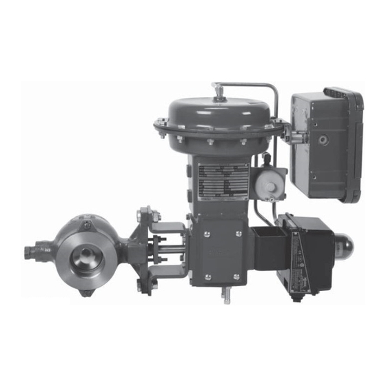
Model 570, 571, 573 Control Valve
Operation, Parts, and Instruction Manual
TABLE OF CONTENTS
Phone: 780
469
4000
•
•
Toll Free: 1
866
396
2356
•
•
•
2
2
3
3
4
5
5
Packing Ring Installation - Figure 4
5
Mounting - Figures 5 / 6
6
7
7
7
8
8
9
9
9
10
10
10
11
12
Fax: 780
469
4035
•
•
P-570M1217B
Website: www.dynafl o.com
12
12
13
13
14
14
14
15
16
16
17
18
19
20
21
22
23
25
26
27
28
36
1
Advertisement
Table of Contents

Subscribe to Our Youtube Channel
Related Manuals for Dyna-Flo 570


Summary of Contents for Dyna-Flo 570
-
Page 1: Table Of Contents
Bearing Driver Tool - Figure 10 / Table 13 Installation Bearing Diagram - Figure 11 Periodic Inspection 570 Cross Section - Figure 12 and 13 Packing Maintenance 571 / 573 Cross Section - Figure 14 Disassembly Packing - Figure 15... -
Page 2: General
Operation, Parts, and Instruction Manual NOTICE These instructions are meant to be used with the Dyna-Flo 570 Series Technical Bulletin as they refer to Figures and Tables therein. If you do not have the Technical Bulletin, contact Dyna-Flo immediately, or visit www.dynafl o.com Each control valve is factory checked. -
Page 3: Specifi Cations
- Square (Optional - 1” to 6” Valves) Refer to Parts for construction materials. - Keyed (Optional - 8” to 12” Valves) Contact your Dyna-Flo sales offi ce for more information and other options. For more information and other options contact your Dyna-Flo sales offi... -
Page 4: Mounting Pad Dimensions - Table
Model 570, 571, 573 Control Valve Operation, Parts, and Instruction Manual MODEL 570 MODEL 571 & 573 SPLINED SHAFT 3” to 12” VALVES 1 - 2” VALVE 8 - 12” VALVE KEYED SHAFT DETAIL 8 - 12” VALVE KEYED SHAFT DETAIL (SQUARE) 1”... -
Page 5: Mounting - Figures
1.25 (31.8) 8 / 10 / 12 0.69 (17.5) 9.25 (235) 1.81 (46.0) Table 5 Model 570, 571, and 573 Square Shaft Dimensions Inch (mm) - Refer to Figure 3. Dimensional Reference Valve Size Inch Consult Dyna-Flo Consult Dyna-Flo Consult Dyna-Flo... - Page 6 Model 570, 571, 573 Control Valve Operation, Parts, and Instruction Manual Table 6 Model 570, 571, and 573 Splined Shaft Dimensions Inch (mm) - Refer to Figure 3. Valve Size Inch 7.38 (188) 1/2 (12.7) 7.38 (188) 7.38 (188) 7.38 (188) 7.38 (188)
-
Page 7: Follower Shaft Pin Diagram - Figure
Model 570, 571, 573 Control Valve Operation, Parts, and Instruction Manual Table 9 Model 571 and 573 Flange Stud Lengths Inch (mm) - Refer to Figures 2 & 3. Valve Size Inch 2.88 (73) 3.12 (79) 3.69 (94) 3.94 (100) 1-1/2 3.12 (80) -
Page 8: 570 Flange Stud Lengths - Table
fl anges, make repairs if necessary. Set the appropriate line gaskets in place. The Model 570 requires the use of long studs that span the Insert the valve into line centering the bottom of the length of the valve and through both line fl anges. The body valve body between the two studs installed in Step 1. -
Page 9: 571 / 573 Flange Stud Lengths - Table
Model 570, 571, 573 Control Valve Operation, Parts, and Instruction Manual INSTALLATION Check for process fl uid leakage to the atmosphere through (Continued) the packing and (if equipped) any NPT connection. Models 571 & 573 Installation (Continued) Examine the valve for damage caused by corrosive fumes or process drippings. -
Page 10: Flange Stud Diameters - Table
Refer to the ball position and the lever position. For Dyna-Flo Assembly / Packing for packing assembly instructions. Model DFR 026 actuators there is no clamp on the lever. -
Page 11: Flange Stud Quantity - Table
Model 570, 571, 573 Control Valve Operation, Parts, and Instruction Manual DISASSEMBLY Always use caution and protect the fl ange gasket surfaces from (Continued) damage during disassembly. Ball Seal Removal (Continued) For 1. 1-1/2, and 2 Inch Valves For Metal Ball Seals Mark the shaft to show the orientation of the ball Remove the seal protector ring screws (Key 12 &... -
Page 12: Bearing Removal
If the bearings (Key 20) need to be replaced, please the valve shafts and valve body for damage as well. note that Dyna-Flo bearing confi gurations have changed for 570 series control valves and new replacement bearing kits will refl ect this change. Bearing Removal NOTE Valve sizes 6, 8, 10, and 12 inch use specifi... -
Page 13: Ball / Shaft
Model 570, 571, 573 Control Valve Operation, Parts, and Instruction Manual ASSEMBLY NOTE (Continued) To prevent trapping air when installing packing Ball / Shaft Assembly rings it is recommended that packing rings be installed one at a time. Do not force packing... -
Page 14: Ball Seal
Model 570, 571, 573 Control Valve Operation, Parts, and Instruction Manual ASSEMBLY Re-install the actuator cover plate and travel indicator (Continued) arrow. Ball Seal Assembly (Continued) For Metal Ball Seals Lubricate the radial seal (Key 7) with white petroleum grease and install it into the groove in the seal protector ring (Key 10). -
Page 15: Packing - Figure
Model 570, 571, 573 Control Valve Operation, Parts, and Instruction Manual Left Hand Mount Figure 5 Mounting Orientation Diagram Figure 6 Actuator/Valve Position Chart Right Hand Mount ACTUATOR VALVE OPEN (diagrams shown using DFR model actuators) STYLE A CLOSE PUSH DOWN TO CLOSE... - Page 16 Model 570, 571, 573 Control Valve Operation, Parts, and Instruction Manual Table 12 Mounting Styles and Positions Position Mounting Action (See Figure 5) Right Hand Mount Fail Open Style A Right Hand Mount Fail Close Style B Left Hand Mount...
- Page 17 Model 570, 571, 573 Control Valve Operation, Parts, and Instruction Manual Figure 8 Ball Seal Assembly Diagrams for Valve Sizes 1 Through 12 Inch VALVE BODY VALVE BODY SEAL PROTECTOR (Key 1) (Key 1) SEAL PROTECTOR (Key 10) RING (Key 10)
- Page 18 Model 570, 571, 573 Control Valve Operation, Parts, and Instruction Manual Figure 9 Ball / Pin Assembly Diagrams for Valve Sizes 1 Through 12 Inch Key 3 BALL ( SHAFT KEY Key 2 Key 18 BALL ( SET SCREW SHAFT PIN...
- Page 19 Model 570, 571, 573 Control Valve Operation, Parts, and Instruction Manual Chamfer 0.015” all Corners AØ BØ Figure 10 Bearing Driver Diagram 0.015” Radius Max (or Under Cut) * Note: for removal this driver will only work if the outboard bearing has a large enough pipe plug to allow access.
- Page 20 Model 570, 571, 573 Control Valve Operation, Parts, and Instruction Manual Figure 11 Old Style Inboard and Outboard Bearing Diagram INBOARD BEARING Key 20 INBOARD BEARING ( Key 19 THRUST WASHER ( SMALLER BEARING RIDGE Key 16 SHAFT ( THRUST WASHER...
- Page 21 Model 570, 571, 573 Control Valve Operation, Parts, and Instruction Manual Figure 12 1 & 1-1/2 Inch Valve Cross Section View rotated for clarity P-570M1217B Dyna-Flo Control Valve Services Ltd. Phone: 780 4000 Toll Free: 1 2356 Fax: 780 4035 Website: www.dynafl...
- Page 22 Model 570, 571, 573 Control Valve Operation, Parts, and Instruction Manual Figure 13 570 Cross Section Detail A - Typical 3 & 4 Inch Valve Construction Detail A - Typical 6 & 8 Inch 2 INCH 570 VALVE DIAGRAM Valve Construction P-570M1217B Dyna-Flo Control Valve Services Ltd.
- Page 23 Model 570, 571, 573 Control Valve Operation, Parts, and Instruction Manual Figure 14 571 & 573 Cross Section Detail A - Typical 3 & 4 Inch Valve Construction Detail A - Typical 6 - 12 Inch 2 INCH 571 & 573 VALVE DIAGRAM...
- Page 24 Model 570, 571, 573 Control Valve Operation, Parts, and Instruction Manual SINGLE SINGLE SINGLE PTFE V-RING PTFE V-RING GRAPHITE PACKING PACKING PACKING VACUUM LIVE LOADED LIVE LOADED PTFE V-RING GRAPHITE PACKING PACKING Figure 15 Packing Confi guration Diagrams (Refer to Figure 15 & 16 for Spring Washer, Key 37, Arrangements) P-570M1217B Dyna-Flo Control Valve Services Ltd.
-
Page 25: Drive Shaft Pin Installation
Model 570, 571, 573 Control Valve Operation, Parts, and Instruction Manual PTFE ARRANGEMENT PTFE ARRANGEMENT PTFE ARRANGEMENT FOR 1/2” & 5/8” SHAFTS FOR 3/4” & 1” SHAFTS FOR 1-1/4” & 1-1/2” SHAFTS Figure 16 Live Loaded PTFE Spring Washer (Key 37) Arrangements... -
Page 26: Follower Shaft Pin Installation
DRIVE SHAFT PIN 1 to 2 inch 570’s uses a 1/4” diameter shaft pin (Key 15)(3/16” diameter for 1” 570’s) to connect the drive shaft to the ball that is precisely fi tted to easily insert into the ball/shaft by hand or with light tapping by a hammer and punch. New ball/shaft assemblies will have the pins inserted loose for easy removal prior to installing into the valve. -
Page 27: Ball / Shaft Assembly
FOLLOWER SHAFT PIN 1, 1-1/2, and 2 inch 570’s follower shaft (Key 13) also uses a straight pin to retain the follower shaft in position. Early designs used a non-stepped 3/16” (1/8” for 1” 570’s) diameter hole in the ball and a longer (1-1/4”) pin which is deformed to allow the pin to tighten in the hole. - Page 28 Model 570, 571, 573 Control Valve Operation, Parts, and Instruction Manual 3 THROUGHT 12 INCH BALL TO SHAFT ASSEMBLY INSTRUCTIONS These instructions outline the recommended procedure for assembly and setting of the ball to shaft connection. Use these instructions when setting or re-setting the ball to shaft connection or when replacing either the ball or shaft. The ball to shaft connection is set prior to assembly.
-
Page 29: Parts
Model 570, 571, 573 Control Valve Operation, Parts, and Instruction Manual Parts -S21800 1 Inch 33B0341X03D Description Part Number 1-1/2 Inch 33B6817X01D Body 2 Inch 33B6676X01D if you need a body as a replacement part, order by 3 Inch 34B4766X01D valve size, serial number and desired material. - Page 30 Model 570, 571, 573 Control Valve Operation, Parts, and Instruction Manual Parts (Continued) 6 Inch 32B3784X01D 8 Inch 32B4378X01D Description Part Number 10 Inch 32B4507X01D Seal Protector Ring 12 Inch 32B4512X01D -CG8M TCM Composition PTFE Seal 1 Inch 34B1721X02D -LCC...
- Page 31 Model 570, 571, 573 Control Valve Operation, Parts, and Instruction Manual Parts (Continued) Follower Shaft Pin S31600 Description Part Number 1 Inch 570X0109X1D Flow Ring (Continued) 1-1/2 Inch 570X200001D -WCC 2 Inch 570X200001D 1 Inch Consult Dyna-Flo 3 Inch 570X300001D...
- Page 32 Model 570, 571, 573 Control Valve Operation, Parts, and Instruction Manual Parts (Continued) Packing Set (See Page 31 for Live Loaded Kits) -PTFE Description Part Number 1 Inch 12A9016X02D Bearing (Continued) 1-1/2 Inch 1R5795X001D 2 Inch 1R5795X001D -S17400 DH1150 / Carbon-fi lled PTFE 3 &...
- Page 33 Model 570, 571, 573 Control Valve Operation, Parts, and Instruction Manual Parts (Continued) Flange Stud Name Plate, Steel NAME11ROTAD Description Part Number NACE Tag, Steel NAME7NACEZD Packing Stud, 2 Required -B8M 1 - 4 Inch 1E94413522D 6 Inch 1E94443525D 8 & 10 Inch...
- Page 34 Model 570, 571, 573 Control Valve Operation, Parts, and Instruction Manual Table 14 Live Loaded Packing Box Parts (Keys 24, 25, 35, 36, 37, 38, 39, 40, 41, 41A) Refer to Figures 15, 16, & 17 Shaft Diameter inch (mm) Description 1/2 (12.7)
- Page 35 Note: Anti-Extrusion Rings (Key 39) are included with the Packing Set. Parts Ordering Whenever corresponding with Dyna-Flo about a 570 Series Control Valves, refer to the nameplate (Key 33) for the serial number of the unit. Please order by the complete part number (as given in the following part lists) of each part required.
-
Page 36: Model Builder
Model 570, 571, 573 Control Valve MODEL NUMBERING SYSTEM S A M P L E PA R T N U M B E R : 570- 2 - C L C - P N T MODEL VALVE SIZE 1 INCH...
Need help?
Do you have a question about the 570 and is the answer not in the manual?
Questions and answers