Table of Contents
Advertisement
Quick Links
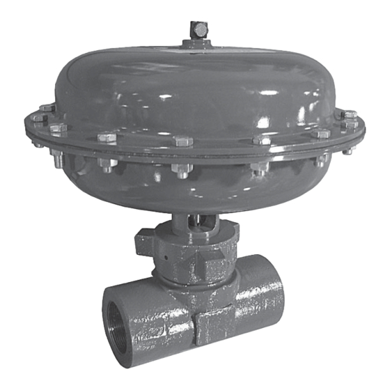
Model DF269 Control Valve
Operation, Parts, and Instruction Manual
Figure 1 DF269 Control
Valve
TABLE OF CONTENTS
Phone: 780
469
4000
•
•
Toll Free: 1
866
396
2356
•
•
•
2
2
2
3
4
4
5
4
5
5
Fax: 780
469
4035
•
•
P-269M0117A
Website: www.dynafl o.com
6
7
8
9
10
10
13
12
13
16
1
Advertisement
Table of Contents

Related Manuals for Dyna-Flo DF269


Summary of Contents for Dyna-Flo DF269
-
Page 1: Table Of Contents
Model DF269 Control Valve Operation, Parts, and Instruction Manual Figure 1 DF269 Control Valve TABLE OF CONTENTS Introduction Fail Open Actuator Disassembly General Body and Packing Reassembly Scope Fail Closed Actuator Resassembly Specifi cations Fail Open Actuator Resassembly Unpacking Gap Diagram Valve Body - Figure 2... -
Page 2: Introduction
INTRODUCTION The Dyna-Flo Model DF269 Control Valve is a rugged globe style control valve intended for demanding applications in process control. It is suitable for a wide range of applications, especially high pressure and severe service. The compact design makes installation and maintenance more convenient than traditional valve and actuator assemblies while still offering the same functionality. -
Page 3: Specifications
Effective Actuator Diaphragm Area 69 inches (452 cm Valve Plug Travel 3/4 inch (19 mm). For more information and other options contact your Dyna-Flo sales offi ce. Maximum Pressure and Temperature Ratings F (93 F (150 NPS 1-2 inch NPT 2,250 Psig (155.13 Bar) -
Page 4: Unpacking
Model DF269 Control Valve Operation, Parts, and Instruction Manual UNPACKING VALVE FROM SHIPPING CAUTION CONTAINER Do not exceed supply pressure indicated on serial plate located on top of the actuator casing (Key 16). Check the packing list against materials received while unpacking the valve. -
Page 5: Body And Packing Disassembly
(Key 24). Once the body (Key 1) is secured, separate the body from the bonnet (Key 2). DF269 bonnets are held in place using A 5/8” wrench is required to remove the stem nut a hammer nut. A small sledge hammer is commonly used (Key 29). -
Page 6: Fail Open Actuator Disassembly
Model DF269 Control Valve Operation, Parts, and Instruction Manual FAIL CLOSED ACTUATOR DISASSEMBLY FAIL OPEN ACTUATOR DISASSEMBLY (Continued) All Key references to follow are from Figures 2 & 4. 16 Remove the hammer nut (Key 30) from over the bonnet, Vent the pneumatic actuator loading pressure if pressure is inspect the threads for damage and corrosion. -
Page 7: Body And Packing Reassembly
16 Remove the hammer nut (Key 30) from over the bonnet, WARNING inspect the threads for damage and corrosion. When reassembling a DF269, the assembly of the actuator must take place with the bonnet / actuator 17 Remove the washer (Key 18) from the hammer nut seating detached from valve. -
Page 8: Fail Closed Actuator Resassembly
WARNING Coat the threads of the valve stem (Key 5) with Nickel When reassembling a Fail Closed DF269, the based anti-seize. Thread the valve plug into the end of the assembly of the actuator must take place with the valve stem until the holes of the plug and stem are in bonnet / actuator detached from valve. -
Page 9: Fail Open Actuator Resassembly
FAIL OPEN ACTUATOR REASSEMBLY (Continued) WARNING When reassembling a Fail Open DF269, the assembly Slide the diaphragm plate (Key 24) over the stem so that it of the actuator must take place with the bonnet / rests with the fl at face against the diaphragm. Reference actuator detached from valve. - Page 10 (Key 3) with mechanical assembly grease. Carefully place the plug into the cage (Key 4) lowering the bonnet Figure 3 DF269 1 Inch Angle Body Diagram assembly into position over the valve. 16 Apply Nickel based anti-seize to the outside threads of the valve body (Key 1).
- Page 11 Operation, Parts, and Instruction Manual Note: Casing (Keys 16 & 17) is rotated 90 to show the NPT connections. Figure 4 DF269 Fail Closed Cross Section with 2 inch NPT Valve Body P-269M0117A Dyna-Flo Control Valve Services Ltd. Phone: 780...
- Page 12 Operation, Parts, and Instruction Manual Note: Casing (Keys 16 & 17) is rotated 90 to show the NPT connections. Figure 5 DF269 Fail Open Cross Section with 1 inch NPT Valve Body P-269M0117A Dyna-Flo Control Valve Services Ltd. Phone: 780...
-
Page 13: Parts
Model DF269 Control Valve Operation, Parts, and Instruction Manual Parts List Description Material Part Number If you need a body as a replacement part, order by valve size, serial Body number and desired material. Bonnet DF20251X01D Valve Plug 1/4 INCH PORT... - Page 14 Model DF269 Control Valve Operation, Parts, and Instruction Manual Parts List Description Material Part Number Upper Diaphragm Casing Steel / Zinc DF20408X01D Lower Diaphragm Casing Steel / Zinc DF20401X01D Bonnet Washer S30200 DF20215X01D Groove Pin S31600 DF40303X01D Cage Bushing S17400 DH1150...
- Page 15 Parts Ordering Whenever corresponding with Dyna-Flo about a Model DF269 control valve, refer to the actuator nameplate or the back of the valve body for the unit serial number. Please order by the complete part number (as given in the Parts List) of each part required.
-
Page 16: Model Builder
Model DF269 Control Valve MODEL NUMBERING SYSTEM S A M P L E PA R T N U M B E R : DF269-1GC3-6BN-14S-X VALVE SIZE 1 INCH 2 INCH BODY STYLE GLOBE STYLE ANGLE STYLE ACTUATOR STYLE FAIL CLOSED...
Need help?
Do you have a question about the DF269 and is the answer not in the manual?
Questions and answers