Table of Contents
Advertisement
Quick Links
Model 361 Control Valves
Operation, Parts, and Instruction Manual
Supplement
The following instructions are to be thoroughly reviewed and understood prior to installing, operating or performing maintenance on
this equipment. Work on this equipment should be performed by experienced personnel. Throughout the manual, safety and caution
notes appear and must be strictly followed to prevent serious injury or equipment malfunction.
These instructions are meant to be used with the Dyna-Flo 361 Technical Sales Bulletin (P-361B0615B) and 360 Operation, Parts,
and Instruction Manual (P-360M0215A) as they refer to Instructions, Figures, Safety Information, and Tables therein. If you do not
have these documents, contact Dyna-Flo immediately, or visit www.dynafl o.com.
The Model 360 Operation, Parts, and Instruction Manual can be used to service Model 361 valves with the exception of
instructions pertaining to the seal ring (Key 34), backup ring (Key 35), and retaining ring (Key 40). Model 361 valves are equipped
with a piston ring (Key 41), or multiple piston rings in place of the above mentioned parts (Keys 34, 35, and 41). Piston rings have
specifi c assembly and disassembly instructions which are covered in this Supplement. All Safety Warnings, Cautions, and Notes
contained within the 360 Instruction Manual will apply to service of the 361 control valve and must be followed.
Dyna-Flo Control Valve Services Ltd.
Phone: 780
469
4000
•
•
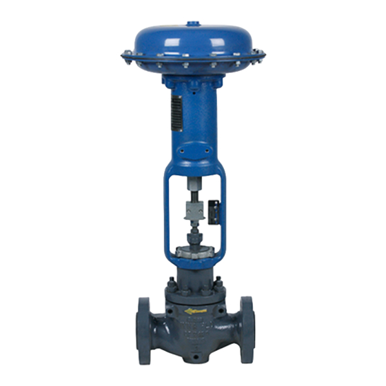
Figure 1 Model 361 Control Valve
Toll Free: 1
866
396
2356
•
•
•
Fax: 780
469
4035
•
•
P-361S0615A
Website: www.dynafl o.com
1
Advertisement
Table of Contents

Subscribe to Our Youtube Channel
Related Manuals for Dyna-Flo 361


Summary of Contents for Dyna-Flo 361
- Page 1 The Model 360 Operation, Parts, and Instruction Manual can be used to service Model 361 valves with the exception of instructions pertaining to the seal ring (Key 34), backup ring (Key 35), and retaining ring (Key 40). Model 361 valves are equipped with a piston ring (Key 41), or multiple piston rings in place of the above mentioned parts (Keys 34, 35, and 41).
- Page 2 Instructions concerning Valve Disassembly (Page 7 of P-360M) Vise Break (See Figure 2) will be the same for Model 361 valves except for Step 1 of Trim Piston rings can be broken into two pieces using a vise with Parts Removal (plug / seat / cage).
- Page 3 Graphite Piston Ring (See Page 4) Key 41 - Multiple Graphite Piston Ring (See Page 4) Figure 1 Model 361 Piston Ring Detail (Refer to P-360M for Key Numbers) P-361S0615A Dyna-Flo Control Valve Services Ltd. Phone: 780 4000 Toll Free: 1...
- Page 4 Our Commitment to Quality Dyna-Flo is committed to continuous improvement. While all efforts have been made to ensure the accuracy of the content in this document, modifi cations or improvements to the information, specifi cations, and designs may occur at any time without notice.
-
Page 5: Table Of Contents
Gasket Descriptions - Table 9 Packing Parts Removal Gasket Kits - Table 10 Body Gasket Removal Packing Repair Kits - Table 11 Lapping Model Builder P-360M0215A Dyna-Flo Control Valve Services Ltd. Phone: 780 4000 Toll Free: 1 2356 Fax: 780 4035 Website: www.dynafl o.com •... -
Page 6: Introduction
Model 360 control valves are cage guided, pressure balanced with push down to close plug action. The actuator typically used for 360 control valves are Dyna-Flo model DFC or DFO linear actuators. These heavy duty actuators are spring return diaphragm style, and can be used for throttling or on/off service, with or without a valve positioner. -
Page 7: Specifications
Valve and Actuator Assembly Dimensions PTFE Seat and Metal Seat Available. See Table 2, 3, and 4 of Sales Bulletin. Consult your Dyna-Flo sales offi ce for other available Approximate Valve Body and Actuator Weights confi gurations. See Table 2 of Sales Bulletin. -
Page 8: Unpacking
Do not exceed maximum casing pressure indicated on serial plate located on the yoke of the actuator or in the Technical (Sales) Bulletin appropriate for the actuator type. P-360M0215A Dyna-Flo Control Valve Services Ltd. Phone: 780 4000 Toll Free: 1... -
Page 9: Periodic Inspection
Make sure positioner linkage (if equipped) and stem connector are securely fastened. If the stem connector is loose, check plug thread engagement and retighten. Refer to the Dyna-Flo Model DFC, or DFO Manual for detailed instructions. Ensure all accessories, mounting brackets and fasteners are secure. -
Page 10: Packing Maintenance
Refer to Valve Disassembly section for Packing Removal Figure 4 Yoke Nut being loosened with a Chisel and Inspection. Refer to Figures 9 and 10 for double and graphite packing arrangements. P-360M0215A Dyna-Flo Control Valve Services Ltd. Phone: 780 4000 Toll Free: 1 2356... -
Page 11: Valve Disassembly
For instructions on Cavitation and Noise Reduction process media from the upstream and downstream Trim contact the Dyna-Flo Sales Offi ce. sides of the valve. Check that bypass valves are used or the process has been completely shut down. -
Page 12: Packing Parts Removal
For three-piece soft seat ring disassembly (Keys 31, 32 & 33) (Continued: The angle on the disk improved by hand lapping. Dyna-Flo recommends the seat that supports the PTFE disk must be in good condition lapping of metal seats on all Model 360 valves when new in order to seal effectively. -
Page 13: Assembly
Any deep scores will require that the plug be Install one-piece or two-piece seal ring (Key 34) machined or replaced. onto plug. P-360M0215A Dyna-Flo Control Valve Services Ltd. Phone: 780 4000 Toll Free: 1 2356 Fax: 780 4035 Website: www.dynafl... -
Page 14: Bonnet Assembly
Graphite ribbon packing damages easily, care is to Key numbers for the following section. For live loaded be taken when installing it into the packing bore. packing instructions refer to the P-LLPS manual. P-360M0215A Dyna-Flo Control Valve Services Ltd. Phone: 780 4000 Toll Free: 1 2356... -
Page 15: Valve Seal Diagram - Figure
310 - 355 (420 - 481) 0.251 - 0.254 (6.38 - 6.45) 1-1/4 (31.8) 610 - 670 (827 - 908) 0.251 - 0.254 (6.38 - 6.45) P-360M0215A Dyna-Flo Control Valve Services Ltd. Phone: 780 4000 Toll Free: 1 2356 Fax: 780 4035 Website: www.dynafl... -
Page 16: Control Valve Cross Section - Figure
1” (25.4 mm) Stem a total of 4 rings. 1-1/4” (31.8 mm) Stem 1-1/4” (31.8 mm) Stem Figure 9 Model 360 Control Valve PTFE Packing Diagrams P-360M0215A Dyna-Flo Control Valve Services Ltd. Phone: 780 4000 Toll Free: 1 2356 Fax: 780 4035 Website: www.dynafl... - Page 17 3/8” (9.5 mm) Stem 1/2” (12.7 mm) Stem 1” (25.4 mm) Stem 1-1/4” (31.8 mm) Stem Figure 10 Model 360 Control Valve Single Style Graphite Packing Diagrams P-360M0215A Dyna-Flo Control Valve Services Ltd. Phone: 780 4000 Toll Free: 1 2356 Fax: 780 4035 Website: www.dynafl...
- Page 18 TWO-PIECE SEAL RING Spring-Loaded Flow Down Flow Up (Cup Faces Down) (Cup Faces Up) Figure 11 Model 360 Control Valve Seal Diagrams P-360M0215A Dyna-Flo Control Valve Services Ltd. Phone: 780 4000 Toll Free: 1 2356 Fax: 780 4035 Website: www.dynafl o.com •...
- Page 19 Operation, Parts, and Instruction Manual YOKE NUT STEM/ VALVE PLUG/PIN DETAIL DETAIL A DETAIL A Soft (PTFE) Seat DYNA-FLO MODEL 360 CONTROL VALVE NACE PACKING ARRANGEMENT Figure 12 Model 360 Control Valve Cross Section METAL SEAT P-360M0215A Dyna-Flo Control Valve Services Ltd.
- Page 20 Figure 13 Detail ‘A’ From Figure 12 - 8 Inch Valve with Load Ring Figure 14 Detail ‘A’ From Figure 12 with Restricted Trim P-360M0215A Dyna-Flo Control Valve Services Ltd. Phone: 780 4000 Toll Free: 1 2356 Fax: 780 4035 Website: www.dynafl...
-
Page 21: Parts
1-1/2 inch 1U22203507D 1-1/4 inch (31.8mm) Stem 1A36812411D 1-1/2 x 1 inch 1U22193507D 2 inch or 3 x 2 inch 1U22263507D P-360M0215A Dyna-Flo Control Valve Services Ltd. Phone: 780 4000 Toll Free: 1 2356 Fax: 780 4035 Website: www.dynafl o.com •... - Page 22 2 inch or 2 x 1 inch (8 Required) 1K2429B7MDD 3 inch or 3 x 2 inch (8 Required) 1A3781B7MDD 4 inch (8 Required) 1R3690B7MDD P-360M0215A Dyna-Flo Control Valve Services Ltd. Phone: 780 4000 Toll Free: 1 2356 Fax: 780 4035 Website: www.dynafl...
- Page 23 1-1/2 x 1 inch (8 Required) 8 inch (16 Required) 2 or 2 x 1 inch (8 Required) -B7M Fluorokote #1 1 inch (4 Required) 1-1/2 inch (8 Required) P-360M0215A Dyna-Flo Control Valve Services Ltd. Phone: 780 4000 Toll Free: 1 2356 Fax: 780 4035 Website: www.dynafl...
- Page 24 6 inch 10A2643X02D S31600/S31603 Dual Grade 8 inch 10A3261X01D 1 inch, 2 x 1 inch 1V71023507D 1-1/2 inch 1V71053507D P-360M0215A Dyna-Flo Control Valve Services Ltd. Phone: 780 4000 Toll Free: 1 2356 Fax: 780 4035 Website: www.dynafl o.com • •...
- Page 25 1U23462201D Adapter Gasket, Graphite 1-1/2 x 1 inch 1U2152X004D 2 x 1 inch 1R3296X004D 3 x 2 inch 1R3481X005D P-360M0215A Dyna-Flo Control Valve Services Ltd. Phone: 780 4000 Toll Free: 1 2356 Fax: 780 4035 Website: www.dynafl o.com • •...
- Page 26 (21A5356X02D) — (21A5362X01D) 1 (25.4) (21A5357X01D) (21A5357X02D) — (21A5363X01D) 1-1/4 (31.8) (21A5358X01D) (21A5358X02D) — (21A5364X01D) P-360M0215A Dyna-Flo Control Valve Services Ltd. Phone: 780 4000 Toll Free: 1 2356 Fax: 780 4035 Website: www.dynafl o.com • • • • • •...
- Page 27 3/4 (19.1) (21A5356X02D) — (21A5362X01D) 1 (25.4) (21A5357X02D) — (21A5363X01D) 1-1/4 (31.8) (21A5358X02D) — (21A5364X01D) P-360M0215A Dyna-Flo Control Valve Services Ltd. Phone: 780 4000 Toll Free: 1 2356 Fax: 780 4035 Website: www.dynafl o.com • • • • • •...
- Page 28 1 - For 3/8 inch stems, remove a packing ring from the lower set for a total of 4 rings. 2 - All S31600 barstock is dual grade S31600/S31603 (316/316L). P-360M0215A Dyna-Flo Control Valve Services Ltd. Phone: 780 4000 Toll Free: 1...
- Page 29 1V6582X005D 11A5350X03D 11A5345X07D 6 x 4 3/4 (19.1) 1V6582X001D (24A9731X03D) (21A5356X05D) (21A5356X05D) 3/4 (19.1) (21A5356X05D) — P-360M0215A Dyna-Flo Control Valve Services Ltd. Phone: 780 4000 Toll Free: 1 2356 Fax: 780 4035 Website: www.dynafl o.com • • • • •...
- Page 30 2U80694893D 2U80684893D 2U80674893D 6 x 4 2V37144893D 2V37124893D 2V37134893D 20A5469X01D 20A5468X01D 20A5467X01D NOTE: Consult Dyna-Flo for other cage characteristics and materials. P-360M0215A Dyna-Flo Control Valve Services Ltd. Phone: 780 4000 Toll Free: 1 2356 Fax: 780 4035 Website: www.dynafl o.com •...
- Page 31 12-1/4 (311) 1K5869NT50D 3 x 2 3/4 (19.1) 14-5/8 (372) 1U2265NT50D 6 x 4 3/4 (19.1) 15-7/8 (403) 1L9964NT50D P-360M0215A Dyna-Flo Control Valve Services Ltd. Phone: 780 4000 Toll Free: 1 2356 Fax: 780 4035 Website: www.dynafl o.com • • •...
-
Page 32: Model Builder
4 inch RGASKETX36D 6 inch RGASKETX37D 8 inch RGASKETX08D 2 x 1 inch RGASKETX25D 3 x 2 inch RGASKETX27D P-360M0215A Dyna-Flo Control Valve Services Ltd. Phone: 780 4000 Toll Free: 1 2356 Fax: 780 4035 Website: www.dynafl o.com • • •... - Page 33 Our Commitment to Quality Dyna-Flo is committed to continuous improvement. While all efforts have been made to ensure the accuracy of the content in this document, modifi cations or improvements to the information, specifi cations, and designs may occur at any time without notice.
- Page 34 Model 360 Control Valve Operation, Parts, and Instruction Manual This page left intentionally blank. P-360M0215A Dyna-Flo Control Valve Services Ltd. Phone: 780 4000 Toll Free: 1 2356 Fax: 780 4035 Website: www.dynafl o.com • • • • • • •...
- Page 35 Model 360 Control Valve Operation, Parts, and Instruction Manual This page left intentionally blank. P-360M0215A Dyna-Flo Control Valve Services Ltd. Phone: 780 4000 Toll Free: 1 2356 Fax: 780 4035 Website: www.dynafl o.com • • • • • • •...
- Page 36 BONNET STYLE STANDARD STANDARD TAPPED EXTENSION STYLE 1 EXTENSION STYLE 2 SHUT-OFF CLASS CLASS IV CLASS V CLASS VI P-360M0215A Dyna-Flo Control Valve Services Ltd. Phone: 780 4000 Toll Free: 1 2356 Fax: 780 4035 Website: www.dynafl o.com • •...
Need help?
Do you have a question about the 361 and is the answer not in the manual?
Questions and answers