Table of Contents
Advertisement
Quick Links
Model 350/351 Control Valves
Operation, Parts, and Instruction Manual
TABLE OF CONTENTS
Dyna-Flo Control Valve Services Ltd.
Phone: 780
469
4000
•
•
Toll Free: 1
866
396
2356
•
•
•
2
2
3
5
6
6
6
7
8
8
9
9
9
11
Model Builder
12
13
Fax: 780
469
4035
•
•
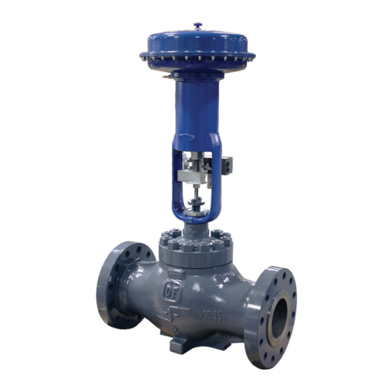
Figure 1 350 Control
Valve & DFC Actuator
P-350M0620A
Website: www.dynafl o.com
14
16
16
16
20
21
22
27
30
31
31
31
32
44
1
Advertisement
Table of Contents

Subscribe to Our Youtube Channel
Related Manuals for Dyna-Flo 350


Summary of Contents for Dyna-Flo 350
-
Page 1: Table Of Contents
Model 350/351 Control Valves Operation, Parts, and Instruction Manual Figure 1 350 Control Valve & DFC Actuator TABLE OF CONTENTS General Lapping Scope Assembly Specifi cations Stud Installation Unpacking Plug Seal Assembly Installation Trim Parts Assembly Air Piping Bonnet Installation... -
Page 2: General
This manual is written to be a practical and useful guide maintaining the Dyna-Flo 350/351 Control Valve. Throughout this manual, unless otherwise specifi ed, references to the Model 350 & 351 will also refer to their “H” confi gurations as well. -
Page 3: Specifications
Operation, Parts, and Instruction Manual SPECIFICATIONS Confi gurations Characteristic and Flow Direction The Model 350/351 control valve is a high capacity single Equal Percentage (Standard) - Flow Down • port, globe style valve, with a bolted type bonnet. Quick Opening - Flow Down •... -
Page 4: Body To Bonnet Stud Torque - Table
Model 350/351 Control Valves Operation, Parts, and Instruction Manual Table 1 Available Valve Confi gurations and Shut-Off Class Valve Size Shut-Off Class Valve Model ASME Class Valve Seat Inch (in accordance with ASME / FCI 70.2) IV (Standard) Metal 6x4, 8x6, 10x8,... -
Page 5: Unpacking
Model 350/351 Control Valves Operation, Parts, and Instruction Manual Table 3 Approximate Valve Body Weights ASME Class Valve Size Connection 150 / 300 (inch) Flanged Buttweld Flanged 1,350 Buttweld 1,000 Flanged 1,250 1,640 10x8 Buttweld 1,130 Flanged 1,102 1,590 12x6... -
Page 6: Installation
If post-weld heat treatment is required, it is recommended that all internal valve Piping Installation Steps: parts be removed from the valve body. Contact Dyna-Flo for Use 3/8” (outside diameter) tubing (or equivalent) for air more information. -
Page 7: Actuator Removal
Model 350/351 Control Valves Operation, Parts, and Instruction Manual Inspection Steps: Refer to the appropriate actuator instruction manual for more information regarding the actuator being removed. Check for visible signs of leakage around all seal and gasket areas. If the valve has been removed from the pipeline, place the valve assembly on a fl... -
Page 8: Maintenance
Model 350/351 Control Valves Operation, Parts, and Instruction Manual For Single PTFE V-Ring Packing (Spring-Loaded): Tighten the packing nuts (Key 39) evenly in an alternating pattern until the shoulder of the packing follower (Key 36) makes contact with the top face of the bonnet (Key 24) and torque value in Table 5 is reached. -
Page 9: Disassembly
Model 350/351 Control Valves Operation, Parts, and Instruction Manual DISASSEMBLY Before You Begin: • Read Safety Caution (Page 2). • Use safe work practices and lock out procedures. • Remove the actuator from the valve (Refer to Actuator Removal Instructions, Page 7). - Page 10 Model 350/351 Control Valves Operation, Parts, and Instruction Manual CHISEL STEP 1 Figure 7 Bonnet Removal (Steps 1 - 2) DISASSEMBLY (Continued) BONNET REMOVAL (Continued) If no process fl uid or gas escapes from the body-to-bonnet joint, proceed by completely removing the bonnet nuts (Key 26).
-
Page 11: Trim Parts Removal
Model 350/351 Control Valves Operation, Parts, and Instruction Manual DISASSEMBLY (Continued) BONNET REMOVAL (Continued) Remove the bonnet spacer (Key 23) if included as part of the valve assembly. For valves with load rings, refer to the Trim Parts Removal section below. -
Page 12: Packing Parts Removal
Model 350/351 Control Valves Operation, Parts, and Instruction Manual PLUG / STEM ASSEMBLY Figure 11 Soft Seat Parts Removal DISASSEMBLY (Continued) PACKING PARTS REMOVAL WARNING: Compressed gasses could be trapped between packing rings. NOTE: For Live Loaded Packing refer to Figure 32 and the Live Loaded Sliding Stem Packing Manual (P-LLPS). -
Page 13: Plug Seal Removal
AREA. DAMAGE TO THE AREA MAY REDUCE OR ELIMINATE THE SEALING FUNCTION OF THE PLUG. Figure 13 Two-Piece Plug Seal Ring Removal (Model 350) Figure 12 Packing Parts Removal (Step 1) DISASSEMBLY (Continued) For Model 350 Three-Piece Seal Ring Assemblies:... -
Page 14: Lapping
Removal (Model 350 Only) DISASSEMBLY (Continued) Figure 15 Model 351 Piston Ring Removal PLUG SEAL REMOVAL (Continued) For Model 350 Three-Piece Plug Seal Ring Assemblies with Anti-Extrusion Rings: LAPPING Carefully remove the retaining ring (Key 10) from the plug Expect a certain amount of leakage in valves with metal groove, a pick set or fl... - Page 15 Model 350/351 Control Valves Operation, Parts, and Instruction Manual LAPPING (Continued) WRENCH Special Tools Required: WRENCH • Soft felt marker • Two wrenches that will slide over the valve stem (Key 5) • 400 – 600 grit (fi ne grit) Loctite...
-
Page 16: Assembly
fi rst, until they are completely WRENCH threaded into the valve body. PLUG SEAL ASSEMBLY For Model 350 Two-Piece Plug Seal Ring Assemblies: Note: Two-piece seals are not available for 8 inch valves. Apply Lubriplate No. 105 (Key C) to the surface of the ®... - Page 17 Operation, Parts, and Instruction Manual NOTE: APPLY GREASE TO ENTIRE OUTSIDE SURFACE OF PLUG BEFORE INSTALLATION. Figure 19 Two-Piece Plug Seal Assembly (Model 350 Only) SPRING-LOADED SEAL RING FOR FLOW DOWN VALVES THE “CUP” OF THE SEAL RING (KEY 8) FACES DOWN.
- Page 18 If one side of the piston ring snaps PLUG SEAL ASSEMBLY (Continued) fi rst, continue compressing the piston ring until the other For Model 350 Three-Piece Plug Seal Ring Assemblies side snaps as well. Refer to Figure 22 for installation. with Anti-Extrusion Rings: Apply Lubriplate No.
- Page 19 Model 350/351 Control Valves Operation, Parts, and Instruction Manual NOTE: STAGGER THE BREAKS IN THE PISTON RINGS. NOTE: APPLY GREASE TO ENTIRE OUTSIDE SURFACE OF PLUG. Figure 22 Model 351 Piston Ring Installation Figure 23 Model 351 Piston Ring Vise Break Method (Step 1)
-
Page 20: Trim Parts Assembly
Model 350/351 Control Valves Operation, Parts, and Instruction Manual ASSEMBLY (Continued) TRIM PARTS ASSEMBLY NOTE: The spiral wound gasket (Key 19) makes its seal by being crushed and cannot be reused. Apply nickel anti-seize (Key A) to the seat ring pocket of the valve body (Key 1). -
Page 21: Bonnet Installation
Model 350/351 Control Valves Operation, Parts, and Instruction Manual ASSEMBLY (Continued) BONNET INSTALLATION (Continued) Apply nickel anti-seize (Key A) to the gasket sealing surface of the valve bonnet (Key 24). Lift and lower the valve bonnet (Key 24) into place over the valve stem (Key 5). -
Page 22: Packing Installation
Model 350/351 Control Valves Operation, Parts, and Instruction Manual ASSEMBLY (Continued) PACKING INSTALLATION For Live Loaded packing instructions refer to the Live Loaded Sliding Stem Packing Manual (Part Number P-LLPS). For other packing arrangements refer to Figures 29, 31, 32, & 33. - Page 23 Model 350/351 Control Valves Operation, Parts, and Instruction Manual ASSEMBLY (Continued) PACKING INSTALLATION (Continued) For Single Style (Spring-Loaded) Packing (Continued): Install the packing fl ange (Key 38). Apply nickel anti-seize (Key A) to the top threads of THE SHOULDER the packing studs (Key 27). Thread the packing nuts (Key...
- Page 24 Model 350/351 Control Valves Operation, Parts, and Instruction Manual ASSEMBLY (Continued) PACKING INSTALLATION (Continued) For Double Style PTFE Packing (Continued): Thread the packing nuts (Key 39) onto the threads of the packing studs, tighten the packing nuts evenly in an alternating pattern until one of the packing nuts reaches the minimum torque requirement shown in Table 5.
- Page 25 Model 350/351 Control Valves Operation, Parts, and Instruction Manual 1/2” (12.7 mm) Stem 3/4” (19.1 mm) Stem 1” (25.4 mm) Stem 1-1/4” (31.8 mm) Stem Figure 32 Live Loaded Packing Example Figure 31 Graphite Packing Arrangement Diagram P-350M0620A Dyna-Flo Control Valve Services Ltd.
- Page 26 Model 350/351 Control Valves Operation, Parts, and Instruction Manual PRESSURE/ PRESSURE VACUUM VACUUM Figure 33 Double PTFE Packing Diagrams P-350M0620A Dyna-Flo Control Valve Services Ltd. Phone: 780 4000 Toll Free: 1 2356 Fax: 780 4035 Website: www.dynafl o.com • •...
- Page 27 Model 350/351 Control Valves Operation, Parts, and Instruction Manual *NOTE: BONNET ROTATED FOR CLARITY. REFER TO FIGURE 19. Figure 34 Model 350 Control Valve Cross Section P-350M0620A Dyna-Flo Control Valve Services Ltd. Phone: 780 4000 Toll Free: 1 2356 Fax: 780 4035 Website: www.dynafl...
- Page 28 Model 350/351 Control Valves Operation, Parts, and Instruction Manual Key 12 - Single Graphite Piston Ring Key 12 - Multiple Graphite Piston Rings Figure 35 Model 351 Piston Ring Detail P-350M0620A Dyna-Flo Control Valve Services Ltd. Phone: 780 4000 Toll Free: 1...
- Page 29 Model 350/351 Control Valves Operation, Parts, and Instruction Manual Figure 36 Extension Bonnet Diagram Figure 37 Load Ring Diagram (8 Inch Valve Assembly) P-350M0620A Dyna-Flo Control Valve Services Ltd. Phone: 780 4000 Toll Free: 1 2356 Fax: 780 4035 Website: www.dynafl o.com •...
- Page 30 Model 350/351 Control Valves DETAIL A DETAIL B Figure 38 Model 350 Control Valve Cross Section - Low Noise Trim P-350M0620A Dyna-Flo Control Valve Services Ltd. Phone: 780 4000 Toll Free: 1 2356 Fax: 780 4035 Website: www.dynafl o.com •...
- Page 31 Model 350/351 Control Valves Table 4 Body to Bonnet Stud Torque Valve Sizes (Inch) Bolt Torques B7M Fluorokote #1 B8M CL2 (annealed) Globe Body B7 Fluorokote #1 ASME Class B8M CL2 (strain hardened) Valves lbf-ft. lbf-ft. lbf-ft. • • •...
-
Page 32: Parts
Model 350/351 Control Valves Operation, Parts, and Instruction Manual Parts Description Part Number -Nitrile Description Part Number 4-3/8 inch port diameter 1V65980305D Body 7 inch port diameter 1V66000305D If you need a body as a replacement part, order by -Ethylene Propylene... - Page 33 Model 350/351 Control Valves Operation, Parts, and Instruction Manual Parts (Continued) Description Part Number -2H Fluorokote #1 Description Part Number 6x4”, body (8 Required) 1A3520XFK1D Seat Ring Refer to Table 12 8x6”, 12x6” body (12 Required) 1A4409XFK1D Disk Seat, Soft Seat Valves, 10x8”, 12x8”...
-
Page 34: Globe Valve Cross Section - Figure
Parts Ordering Whenever corresponding with Dyna-Flo about a 350 Series Control Valves, refer to the nameplate (Key 45) or name tag (Key 44) for the serial number of the unit. Please order by the complete part number (as given in the part lists) of each part required. - Page 35 Consult Dyna-Flo 1 - Standard option. Notes: - All S31600 barstock is dual grade S31600/S31603 (316/316L). Table 8 Model 350 Valve Plug (Key 3) - Three-Piece Seal Ring (Except Anti-Cavitation Construction) Plug Material Stem Diameter Valve Size S31600 / Alloy 6...
- Page 36 Model 350/351 Control Valves Operation, Parts, and Instruction Manual Table 9 Model 351 Valve Plug (Key 3) - Piston Ring Construction Plug Material Stem Diameter Valve Size S31600 / Alloy 6 S31600 / Alloy 6 Inch S41600 HT S31600 Seat Seat &...
- Page 37 Model 350/351 Control Valves Operation, Parts, and Instruction Manual Table 10 Cage (Key 18) - Except for Anti-Cavitation and Low-Noise III Construction Cage Material Valve Size Characteristic Inch S17400 H900 S17400 DH1150 S31600/ENC Equal Percent 2U23633327D 2U23631150D 2U74134893D Linear 2U23663327D...
-
Page 38: Low Noise Trim Cross Section - Figure
Model 350/351 Control Valves Operation, Parts, and Instruction Manual Table 11 Stem (Key 5) - S20910 - Except for Anti-Cavitation Construction Bonnet Style Valve Size Stem Diameter Standard Style 1 Extension Style 2 Extension Inch Inch 12.7 1U2305NT50D 1U2306NT50D 1U2307NT50D 19.1... - Page 39 Model 350/351 Control Valves Operation, Parts, and Instruction Manual Table 11 (Continued) Stem (Key 5) - S20910 - Except for Anti-Cavitation Construction Bonnet Style Valve Size Stem Diameter Standard Style 1 Extension Style 2 Extension Inch Inch 19.1 Consult Dyna-Flo...
- Page 40 12 x 6 10 x 8 RGASKETX23D 12 x 8 - All S31600 barstock is dual grade S31600/S31603 (316/316L). Notes: Low-Noise III trim requires 2 bonnet gaskets (Key 21). Consult Dyna-Flo. Table 15 Packing Repair Kits Single Double Stem Diameter [Yoke...
- Page 41 Our Commitment to Quality Dyna-Flo is committed to continuous improvement. While all efforts have been made to ensure the accuracy of the content in this document, modifi cations or improvements to the information, specifi cations, and designs may occur at any time without notice.
- Page 42 Model 350/351 Control Valves MODEL NUMBERING SYSTEM S A M P L E PA R T N U M B E R : 3 5 0 - 6 4 A F L - 5 P 2 - V E S 4...
Need help?
Do you have a question about the 350 and is the answer not in the manual?
Questions and answers