Table of Contents
Advertisement
Quick Links
Model 360/361 Control Valves
Operation, Parts, and Instruction Manual
TABLE OF CONTENTS
Phone: 780
469
4000
•
•
Toll Free: 1
866
396
2356
•
•
•
2
2
3
5
5
6
7
7
8
8
9
9
9
11
11
12
Fax: 780
469
4035
•
•
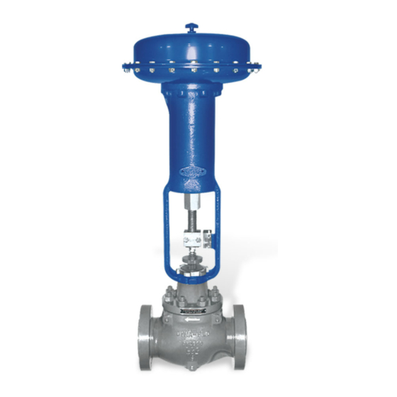
Figure 1 360 Control
Valve & DFC Actuator
P-360M1019A
Website: www.dynafl o.com
13
15
15
15
19
20
21
26
28
32
32
32
33
49
1
Advertisement
Table of Contents

Subscribe to Our Youtube Channel
Related Manuals for Dyna-Flo 360


Summary of Contents for Dyna-Flo 360
-
Page 1: Table Of Contents
Model 360/361 Control Valves Operation, Parts, and Instruction Manual Figure 1 360 Control Valve & DFC Actuator TABLE OF CONTENTS General Lapping Scope Assembly Specifi cations Stud Installation Unpacking Plug Seal Assembly Installation Trim Parts Assembly Air Piping Bonnet Installation... -
Page 2: General
Some material combinations are limited in their pressure and temperature ranges. Do not apply any other conditions to the valve without fi rst contacting your Dyna-Flo sales offi ce. This manual is written to be a practical and useful guide to maintaining the Dyna-Flo 360 Control Valve. SAFETY CAUTION Only well trained experienced technicians should perform these procedures. -
Page 3: Specifications
Operation, Parts, and Instruction Manual SPECIFICATIONS Confi gurations Dimensions The Model 360 control valve is a high capacity single port, Valve and Actuator Outline Dimension Diagram globe style valve with a bolted type bonnet. The standard Refer to Figure 2 of the Sales Bulletin. - Page 4 Model 360/361 Control Valves Operation, Parts, and Instruction Manual Table 1 Available Valve Confi gurations End Connection Valve Size Valve Model and RTJ (Flanged) Inch ASME Class 150 ASME Class 300 ASME Class 600 ...
-
Page 5: Unpacking
fl ow arrow on the valve body. treatment is required, it is recommended that all internal valve Install the appropriate line fl ange gaskets. parts be removed from the valve body. Contact Dyna-Flo for more information. Apply Permatex Nickel Anti-Seize to the threads of the ®... -
Page 6: Air Piping
Model 360/361 Control Valves Operation, Parts, and Instruction Manual INSTALLATION (Continued) AIR PIPING WARNING: Property damage, environmental harm, and personal injury can result from the use of supply gas other than clean, non-corrosive, oil and moisture free air. Do not exceed the supply pressure indicated on the serial plate located on the actuator. -
Page 7: Periodic Inspection
Model 360/361 Control Valves Operation, Parts, and Instruction Manual PERIODIC INSPECTION ACTUATOR REMOVAL Note: Actuator removal does not require that the valve be Special Equipment Required: removed from the pipeline. • Bypass or block valves. Tools Needed: Before You Begin: •... -
Page 8: Maintenance
Model 360/361 Control Valves Operation, Parts, and Instruction Manual For Single PTFE V-Ring Packing (Spring-Loaded): Tighten the packing nuts (Key 38) evenly in an alternating pattern until the shoulder of the packing follower (Key 35) makes contact with the top face of the bonnet (Key 26). -
Page 9: Disassembly
Model 360/361 Control Valves Operation, Parts, and Instruction Manual DISASSEMBLY Before You Begin: • Read Safety Caution (Page 2). • Use safe work practices and lock out procedures. • Remove the actuator from the valve (Refer to Actuator Removal Instructions, Page 7). - Page 10 Model 360/361 Control Valves Operation, Parts, and Instruction Manual CHISEL STEP 1 Figure 7 Bonnet Removal (Steps 1 - 2) DISASSEMBLY (Continued) BONNET REMOVAL (Continued) If no process fl uid or gas escapes from the body-to-bonnet joint proceed by completely removing the bonnet nuts (Key 28).
-
Page 11: Trim Parts Removal
Model 360/361 Control Valves Operation, Parts, and Instruction Manual DISASSEMBLY (Continued) TRIM PARTS REMOVAL PLUG / STEM For Reduced Trim: ASSEMBLY Remove the cage adapter ring (Key 24). Refer to Figure 37. NOTE: 6x4 inch valve do not use a cage adapter. -
Page 12: Plug Seal Removal
fl at screw driver may be required. damaged, all other packing parts should be replaced. BLUNT Figure 11 Two-Piece Plug Seal Ring Removal (Model 360) For Model 360 Three-Piece Seal Ring Assemblies: NOTE: 8 inch valve assemblies have only one-piece plug seals, they only use a seal ring (Key 8). -
Page 13: Lapping
Removal (Model 360 Only) DISASSEMBLY (Continued) Figure 13 Model 361 Piston Ring Removal PLUG SEAL REMOVAL (Continued) For Model 360 Three-Piece Plug Seal Ring Assemblies with Anti-Extrusion Rings: LAPPING Carefully remove the retaining ring (Key 10) from the plug, Expect a certain amount of leakage in valves with metal a pick set or fl... - Page 14 Model 360/361 Control Valves Operation, Parts, and Instruction Manual LAPPING (Continued) WRENCH WRENCH Special Tools Required: • Soft felt marker • Two wrenches that will slide over the valve stem (Key 5) • 400 – 600 grit (fi ne grit) Loctite...
-
Page 15: Assembly
fi rst, until they are completely WRENCH threaded into the valve body. PLUG SEAL ASSEMBLY For Model 360 Two-Piece Plug Seal Ring Assemblies: Note: Two-piece seals are not available for 8 inch valves. Apply Lubriplate No. 105 (Key C) to the surface of the ®... - Page 16 Operation, Parts, and Instruction Manual NOTE: APPLY GREASE TO ENTIRE OUTSIDE SURFACE OF PLUG BEFORE INSTALLATION. Figure 17 Two-Piece Plug Seal Assembly (Model 360 Only) SPRING-LOADED SEAL RING FOR FLOW DOWN VALVES - THE “CUP” OF THE SEAL RING (KEY 8) FACES DOWN.
- Page 17 If one side of the piston ring snaps fi rst, continue compressing the piston ring until the other PLUG SEAL ASSEMBLY (Continued) side snaps as well. For Model 360 Three-Piece Plug Seal Ring Assemblies with Anti-Extrusion Rings: Piston Ring Scoring Break Method: Apply Lubriplate No.
- Page 18 Model 360/361 Control Valves Operation, Parts, and Instruction Manual NOTE: STAGGER THE BREAKS IN THE PISTON RINGS. NOTE: APPLY GREASE TO ENTIRE OUTSIDE SURFACE OF PLUG. Figure 20 Model 361 Piston Ring Installation Figure 21 Model 361 Piston Ring Vise Break Method (Step 1)
-
Page 19: Trim Parts Assembly
Model 360/361 Control Valves Operation, Parts, and Instruction Manual ASSEMBLY (Continued) For Reduced Trim: Install the cage adapter (Key 24). Apply nickel anti-seize (Key A) to the top of the cage TRIM PARTS ASSEMBLY adapter and top surface of the cage adapter gasket (Key NOTE: Spiral wound gaskets (Keys 20) make their seal by 25) and install. -
Page 20: Bonnet Installation
Model 360/361 Control Valves Operation, Parts, and Instruction Manual ASSEMBLY (Continued) BONNET INSTALLATION (Continued) Apply nickel anti-seize (Key A) to the gasket sealing surface of the valve bonnet (Key 26). Lift and lower the valve bonnet (Key 26) into place over the valve stem (Key 5). -
Page 21: Packing Installation
Model 360/361 Control Valves Operation, Parts, and Instruction Manual ASSEMBLY (Continued) PACKING INSTALLATION For Live Loaded packing instructions see the Live Loaded Sliding Stem Packing Manual (Part Number P-LLPS). For other packing arrangements refer to Figures 27, 29, 30, & 31. - Page 22 Model 360/361 Control Valves Operation, Parts, and Instruction Manual ASSEMBLY (Continued) PACKING INSTALLATION (Continued) For Single Style (Spring-Loaded) Packing (Continued): Install the packing fl ange (Key 35). Apply nickel anti-seize (Key A) to the top threads of THE SHOULDER the packing studs (Key 29). Thread the packing nuts (Key...
- Page 23 Model 360/361 Control Valves Operation, Parts, and Instruction Manual ASSEMBLY (Continued) PACKING INSTALLATION (Continued) For Double Style PTFE Packing (Continued): Thread the packing nuts (Key 38) onto the threads of the packing studs, tighten the packing nuts evenly in an alternating pattern until one of the packing nuts reaches the minimum torque requirement shown in Table 6.
- Page 24 PRESSURE/ VACUUM PRESSURE VACUUM *For 3/8 inch stems, remove a packing ring from the lower set for a total of 4 rings. Figure 29 Model 360 Control Valve PTFE Packing Diagrams P-360M1019A Dyna-Flo Control Valve Services Ltd. Phone: 780 4000...
- Page 25 Model 360/361 Control Valves Operation, Parts, and Instruction Manual 3/8” (9.5 mm) Stem 3/4” (19.1 mm) Stem 1” (25.4 mm) Stem 1/2” (12.7 mm) Stem 1-1/4” (31.8 mm) Stem Figure 31 Live Loaded Packing Example Figure 30 Graphite Packing Arrangement Diagram P-360M1019A Dyna-Flo Control Valve Services Ltd.
- Page 26 Model 360/361 Control Valves Operation, Parts, and Instruction Manual *NOTE: BONNET ROTATED FOR CLARITY. REFER TO FIGURE 17. Figure 32 Model 360 Control Valve Cross Section P-360M1019A Dyna-Flo Control Valve Services Ltd. Phone: 780 4000 Toll Free: 1 2356 Fax: 780 4035 Website: www.dynafl...
- Page 27 Model 360/361 Control Valves Operation, Parts, and Instruction Manual Key 48 - Single Graphite Piston Ring Key 48 - Multiple Graphite Piston Ring Figure 33 Model 361 Piston Ring Detail P-360M1019A Dyna-Flo Control Valve Services Ltd. Phone: 780 4000 Toll Free: 1...
- Page 28 Model 360/361 Control Valves Operation, Parts, and Instruction Manual Figure 34 Angle Body Valve Cross Section *NOTE: BONNET ROTATED FOR CLARITY. REFER TO FIGURES 23 & 37 REFER TO FIGURE 17 P-360M1019A Dyna-Flo Control Valve Services Ltd. Phone: 780 4000...
- Page 29 Operation, Parts, and Instruction Manual NOTE: KEY 8, SEAL ‘CUP’ FACES UP. *NOTE: BONNET ROTATED FOR CLARITY. Figure 35 Model 360 Low-Noise Control Valve with Bonnet Spacer Cross Section P-360M1019A Dyna-Flo Control Valve Services Ltd. Phone: 780 4000 Toll Free: 1...
- Page 30 Model 360/361 Control Valves Operation, Parts, and Instruction Manual Figure 37 Restricted Trim / Soft Seat Diagram Figure 38 Soft Seat Diagram Figure 36 Extension Bonnet Diagram P-360M1019A Dyna-Flo Control Valve Services Ltd. Phone: 780 4000 Toll Free: 1 2356...
- Page 31 Model 360/361 Control Valves Operation, Parts, and Instruction Manual Figure 39 Restricted Trim Metal Seat Design Figure 40 Load Ring Diagram (8 Inch Valve Assembly) P-360M1019A Dyna-Flo Control Valve Services Ltd. Phone: 780 4000 Toll Free: 1 2356 Fax: 780 4035 Website: www.dynafl...
-
Page 32: Globe Valve Cross Section - Figure
Model 360/361 Control Valves Operation, Parts, and Instruction Manual Table 5 Body to Bonnet Stud Torque Valve Sizes (Inch) Bolt Torques B7M Fluorokote #1 B8M CL1 (annealed) Globe Body Angle Body B7 Fluorokote #1 B8M CL2 (strain hardened) Valves Valves lbf-ft. -
Page 33: Parts
Model 360/361 Control Valves Operation, Parts, and Instruction Manual Parts Description Part Number 1 inch (4 Required) 1R2848XFK3D Description Part Number 1-1/2 inch (8 Required) 1K2429XFK3D Body 2 inch (8 Required) 1K2429XFK3D If you need a body as a replacement part, order by... -
Page 34: Angle Valve Cross Section - Figure
Model 360/361 Control Valves Operation, Parts, and Instruction Manual Parts (Continued) Description Part Number Gasket, Seat Ring, S31600/Graphite Description Part Number 1 inch 1R2862X011D Seal Ring, Two-Piece Plug Seal (Continued) 1-1/2 inch 1R3098X005D - Carbon-fi lled PTFE (Standard) 2 inch... - Page 35 Model 360/361 Control Valves Operation, Parts, and Instruction Manual Parts (Continued) Description Part Number 4 inch (8 Required) 1A35202HMDD Description Part Number 6 inch (12 Required) 1A44092HMDD Gasket, Body/Bonnet, S31600/Graphite 8 inch (16 Required) 1A44522HMDD 1 inch 1R2859X004D 1-1/2 inch...
- Page 36 Baffl e Contact Dyna-Flo 1 inch (25.4 mm) Stem 1J87290633D Low-Noise III A3, B3, C3 Trim Packing Flange 49/50 Cage Retainer/Baffl e Assembly Contact Dyna-Flo -Carbon Steel - Plated Low-Noise III D3 3/8 inch (9.5 mm) Stem 1E94372410D (12.7mm) Stem...
- Page 37 NOTE: Not all the available replacement part numbers are shown in this manual, if you have inquiries about parts that are not listed please contact your Dyna-Flo Sales Representative. Table 8 360 Globe Valve Plug / Stem* Assembly Standard Temperature (Keys 3, 4, & 5) - For Two-Piece Plug Seals with Standard Bonnets Valve Size...
- Page 38 Model 360/361 Control Valves Operation, Parts, and Instruction Manual Table 9 360 Globe Valve Plug / Stem* Assembly Standard Temperature (Keys 3, 4, & 5) - For Two-Piece Plug Seals with Style 1 Extension Bonnets Valve Size Port Size Stem Diameter...
- Page 39 Model 360/361 Control Valves Operation, Parts, and Instruction Manual Table 10 360 Globe Valve Plug / Stem* Assembly Standard Temperature (Keys 3, 4, & 5) - For Three-Piece Plug Seals without Anti-Extrusion Rings (Standard Bonnets) Valve Size Port Size Stem Diameter...
- Page 40 Model 360/361 Control Valves Operation, Parts, and Instruction Manual Table 11 360 Globe Valve Plug / Stem* Assembly Standard Temperature (Keys 3, 4, & 5) - Three-Piece Plug Seals with Anti-Cavitation 2 Stage (Standard Bonnets) Valve Size Port Size Stem Diameter...
- Page 41 Model 360/361 Control Valves Operation, Parts, and Instruction Manual Table 13 360 Globe Valve Plug / Stem* Assembly High Temperature (Keys 3, 4, & 5) - For Three-Piece Plug Seals with Anti-Extrusion Rings (Standard Bonnets) - No Radius on Plug Seat Valve Size...
- Page 42 Operation, Parts, and Instruction Manual Table 14 360 Globe Valve Plug / Stem* Assembly High Temperature (Keys 3, 4, & 5) - For Three-Piece Plug Seals with Anti-Extrusion Rings (Style 1 Extension Bonnets) - No Radius on Plug Seat Valve Size...
- Page 43 Model 360/361 Control Valves Operation, Parts, and Instruction Manual Table 15 361 Globe Valve Plug / Stem* Assembly Standard Temperature (Keys 3, 4, & 5) - For Double Piston Rings with Standard Bonnets Valve Size Port Size Stem Diameter Travel...
- Page 44 Model 360/361 Control Valves Operation, Parts, and Instruction Manual Table 16 361 Globe Valve Plug / Stem* Assembly Standard Temperature (Keys 3, 4, & 5) - For Double Piston Rings with Style 1 Extension Bonnets Valve Size Port Size Stem Diameter...
- Page 45 Model 360/361 Control Valves Operation, Parts, and Instruction Manual Table 17 361 Globe Valve Plug / Stem* Assembly High Temperature (Keys 3, 4, & 5) - For Double Piston Rings with Standard Bonnets Valve Size Port Size Stem Diameter Travel...
- Page 46 Model 360/361 Control Valves Operation, Parts, and Instruction Manual Table 18 361 Globe Valve Plug / Stem* Assembly High Temperature (Keys 3, 4, & 5) - For Double Piston Rings with Style 1 Extension Bonnets Valve Size Port Size Stem Diameter...
- Page 47 Model 360/361 Control Valves Operation, Parts, and Instruction Manual Table 19 Cage (Key 19) - 360 Quick Opening Valve Size Inch Port Size Cage Material Globe Body Angle Body Inch (mm) S17400 H900 S17400 DH1150 S31600 / ENC 1, 1-1/2x1, 2x1 1, 2x1 1-5/16 (33.3)
- Page 48 2V37231150D 2V37134893D 8 (203.2) 20A3245X01D 20A3245X05D 20A5467X01D - All S31600 barstock is dual grade S31600/S31603 (316/316L). Table 22 Cage (Key 19) - 360 Anti-Cavitation (S17400 H900 Cage Material) Valve Size Port Size Stage Inch Inch (mm) Stage 1 1 (25.4)
-
Page 49: Model Builder
Model 360/361 Control Valves Operation, Parts, and Instruction Manual Table 24 Cage (Key 19) - 361 Equal Percentage - Double Piston Ring Valve Size Inch Port Size Cage Material Globe Body Inch (mm) S17400 H900 S17400 DH1150 S31600 / ENC 1, 1-1/2x1, 2x1 1-5/16 (33.3) - Page 50 Model 360/361 Control Valves Operation, Parts, and Instruction Manual Table 26 Cage (Key 19) - 361 Quick Opening - Double Piston Ring Valve Size Inch Port Size Cage Material Globe Body Inch (mm) S17400 H900 S17400 DH1150 S31600 / ENC 1, 1-1/2x1, 2x1 1-5/16 (33.3)
- Page 51 Model 360/361 Control Valves Operation, Parts, and Instruction Manual Table 28 Seat Ring (Keys 15) - For Standard Trim Material Globe Body Angle Body Inch Inch S41600 HT S31600 S31600 / Alloy 6 Hard Faced Seat 1, 2 x 1...
- Page 52 RGASKETX28D RGASKETX37D 6 x 4 RGASKETX37D RGASKETX23D - All S31600 barstock is dual grade S31600/S31603 (316/316L). NOTE: Low-Noise III trim requires 2 bonnet gaskets (Key 22). Consult Dyna-Flo. P-360M1019A Dyna-Flo Control Valve Services Ltd. Phone: 780 4000 Toll Free: 1...
- Page 53 Model 360/361 Control Valves Operation, Parts, and Instruction Manual Table 32 Packing Parts (Keys 32, 33, 34, 39, 40, & 41) PTFE Packing Stem Diameter Inch (mm) Key # Description 3/8 (9.5) 1/2 (12.7) 3/4 (19.1) 1 (25.4) Part #...
- Page 54 Our Commitment to Quality Dyna-Flo is committed to continuous improvement. While all efforts have been made to ensure the accuracy of the content in this document, modifi cations or improvements to the information, specifi cations, and designs may occur at any time without notice.
- Page 55 Model 360/361 Control Valves MODEL NUMBERING SYSTEM S A M P L E PA R T N U M B E R : 3 6 1 - 3 A F L - 2 F P 2 - G E S 2...
- Page 56 Model 360/361 Control Valves MODEL NUMBERING SYSTEM S A M P L E PA R T N U M B E R : 3 6 0 - 3 A F L - 5 F P 2 - V E S 4...
Need help?
Do you have a question about the 360 and is the answer not in the manual?
Questions and answers