Table of Contents
Advertisement
Quick Links
Model 390, 391, 392 Control Valves
Operation, Parts, and Instruction Manual
TABLE OF CONTENTS
Phone: 780
469
4000
•
•
Toll Free: 1
866
396
2356
•
•
•
2
2
3
4
4
5
6
6
7
7
8
8
8
9
10
11
12
Fax: 780
469
4035
•
•
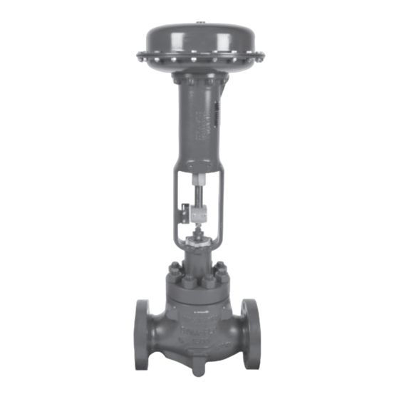
Figure 1 390 Control
Valve & DFC Actuator
P-390M0620A
Website: www.dynafl o.com
13
13
13
16
16
19
23
24
26
26
26
27
43
44
1
Advertisement
Table of Contents

Subscribe to Our Youtube Channel
Related Manuals for Dyna-Flo 390


Summary of Contents for Dyna-Flo 390
-
Page 1: Table Of Contents
Model 390, 391, 392 Control Valves Operation, Parts, and Instruction Manual Figure 1 390 Control Valve & DFC Actuator TABLE OF CONTENTS General Assembly Scope Stud Installation Specifi cations Plug Seal Assembly Unpacking Trim Parts Assembly Installation Bonnet Installation Air Piping... -
Page 2: General
Operation, Parts, and Instruction Manual NOTICE These instructions are meant to be used with the Dyna-Flo 390 Technical Bulletin as they refer to Figures and Tables therein. If you do not have the Technical Bulletin, contact Dyna-Flo immediately, or visit www.dynafl... -
Page 3: Specifications
SPECIFICATIONS Confi gurations Approximate Valve Body and Actuator Weights The Model 390 control valve is a high capacity single port, Refer to Table 1. globe style valve with a bolted type bonnet. The standard valve plug action is push down to close. Refer to Table 1 of the Sales Bulletin. -
Page 4: Unpacking
If post-weld heat treatment is required, it is recommended that all internal valve Install the appropriate line fl ange gaskets. parts be removed from the valve body. Contact Dyna-Flo for more information. Apply anti-seize compound to the threads of the fl ange studs and install. -
Page 5: Air Piping
Model 390, 391, 392 Control Valves Operation, Parts, and Instruction Manual INSTALLATION (Continued) AIR PIPING WARNING: Property damage, environmental harm, and personal injury can result from the use of supply gas other than clean, non-corrosive, oil and moisture free air. Do not exceed the supply pressure indicated on the serial plate located on the actuator. -
Page 6: Periodic Inspection
Model 390, 391, 392 Control Valves Operation, Parts, and Instruction Manual PERIODIC INSPECTION ACTUATOR REMOVAL Note: Actuator removal does not require that the valve be Special Equipment Required: removed from the pipeline. • Bypass or block valves. Tools Needed: Before You Begin: •... -
Page 7: Maintenance
Model 390, 391, 392 Control Valves Operation, Parts, and Instruction Manual For Single PTFE V-Ring Packing (Spring-Loaded): Tighten the packing nuts (Key 25) evenly in an alternating pattern until the shoulder of the packing follower (Key 22) makes contact with the top face of the bonnet (Key 14). -
Page 8: Disassembly
Model 390, 391, 392 Control Valves Operation, Parts, and Instruction Manual DISASSEMBLY Before You Begin: • Read Safety Caution (Page 2). • Use safe work practices and lock out procedures. • Remove the actuator from the valve (Refer to Actuator Removal Instructions, Page 6). -
Page 9: Trim Parts Removal
Remove the valve stem (Key 5) / valve plug (Key 3) assembly from the valve body (Key 1). Refer to Plug Seal Removal section for instructions for disassembling Model 390 and 391 plug seals. Model 392 plugs do not have seals. Remove the bonnet gasket (Key 13). -
Page 10: Plug Seal Removal
Remove the anti-extrusion ring (Key 39). The anti- Clean and inspect all parts for damage, especially gasket extrusion ring is only included in 390 valve assemblies seal surfaces. Replace all damaged parts and gaskets with rated for over 450°F (232°C). -
Page 11: Packing Parts Removal
Model 390, 391, 392 Control Valves Operation, Parts, and Instruction Manual DISASSEMBLY (Continued) PACKING PARTS REMOVAL WARNING: Compressed gasses could be trapped between packing rings. Using a blunt or rounded tool or rod, carefully tap the packing parts (Keys 21, 20, 19, 18, and 17) out of the packing bore of the bonnet (Key 14). -
Page 12: Lapping
Model 390, 391, 392 Control Valves Operation, Parts, and Instruction Manual LAPPING Install the jam nut (Key 29) on to the valve stem (Key 5) and build a handle as shown in Figure 14 and 16 Expect a certain amount of leakage in valves with metal using the two wrenches and the hex nut (Key 30). -
Page 13: Assembly
Model 390, 391, 392 Control Valves Operation, Parts, and Instruction Manual ASSEMBLY Before You Begin: • Read Safety Caution (Page 2). • Use safe work practices and lock out procedures. APPLY FINE • Clean and inspect all parts. GRIT LAPPING •... - Page 14 VALVES - THE “CUP” OF THE OUTSIDE SEAL RINGS (KEY 6) FACE SURFACE OF EACH OTHER. PLUG. Figure 17 Model 390 Plug Seal Standard Assembly ASSEMBLY (Continued) NOTE: KEY 39 IS TWO PLUG SEAL ASSEMBLY (Continued) PIECES AND MUST BE...
- Page 15 Model 390, 391, 392 Control Valves Operation, Parts, and Instruction Manual ASSEMBLY (Continued) PLUG SEAL ASSEMBLY (Continued) For Model 391 Valves (Continued): Piston Ring Scoring Break Method: If no vise is available, piston rings (Key 9) can be scored with a knife and broken over a hard surface.
-
Page 16: Trim Parts Assembly
Model 390, 391, 392 Control Valves Operation, Parts, and Instruction Manual KEY 10, 11, 12, & 13 ANTI-SEIZE DETAIL ASSEMBLY (Continued) TRIM PARTS ASSEMBLY NOTE: Spiral wound gaskets (Keys 10 & 13) make their seal by being crushed and cannot be reused. - Page 17 Model 390, 391, 392 Control Valves Operation, Parts, and Instruction Manual ASSEMBLY (Continued) BONNET INSTALLATION (Continued) correct areas that need more tightening or less. The packing follower should remain centered during the torquing process. Follow proper body-to-bonnet bolting procedures. Begin to torque the bonnet nuts (Key 15) ¼...
- Page 18 Model 390, 391, 392 Control Valves Operation, Parts, and Instruction Manual ASSEMBLY (Continued) PACKING INSTALLATION For Live Loaded packing instructions see the Live Loaded Sliding Stem Packing Manual (Part Number P-LLPS). For other packing arrangements refer to Figures 26, 28, 29, & 30.
-
Page 19: Packing Installation
Model 390, 391, 392 Control Valves Operation, Parts, and Instruction Manual ASSEMBLY (Continued) PACKING INSTALLATION (Continued) For Single Style (Spring-Loaded) Packing (Continued): Install the packing fl ange (Key 24). Apply anti-seize compound (Key A) to the top threads of the packing studs (Key 16). Thread the packing nuts (Key... - Page 20 Model 390, 391, 392 Control Valves Operation, Parts, and Instruction Manual ASSEMBLY (Continued) PACKING INSTALLATION (Continued) For Double Style PTFE Packing (Continued): Thread the packing nuts (Key 25) onto the threads of the packing studs, tighten the packing nuts evenly in an alternating pattern until one of the packing nuts reaches the minimum torque requirement shown in Table 3.
- Page 21 PRESSURE/ VACUUM PRESSURE VACUUM *For 3/8 inch stems, remove a packing ring from the lower set for a total of 4 rings. Figure 28 390 Series Control Valve PTFE Packing Diagrams P-390M0620A Dyna-Flo Control Valve Services Ltd. Phone: 780 4000...
- Page 22 Model 390, 391, 392 Control Valves Operation, Parts, and Instruction Manual 3/8” (9.5 mm) Stem 3/4” (19.1 mm) Stem 1” (25.4 mm) Stem 1/2” (12.7 mm) Stem 1-1/4” (31.8 mm) Stem Figure 30 Live Loaded Packing Example Figure 29 Single Graphite Packing Arrangement P-390M0620A Dyna-Flo Control Valve Services Ltd.
-
Page 23: Globe Valve Cross Section
Model 390, 391, 392 Control Valves Operation, Parts, and Instruction Manual *NOTE: BONNET ROTATED FOR CLARITY. FIGURE Figure 31 Model 390 Control Valve Cross Section P-390M0620A Dyna-Flo Control Valve Services Ltd. Phone: 780 4000 Toll Free: 1 2356 Fax: 780 4035 Website: www.dynafl... -
Page 24: Angle Valve Cross Section
Model 390, 391, 392 Control Valves Operation, Parts, and Instruction Manual Figure 32 Model 390 Angle Valve with Extension Bonnet *NOTE: BONNET ROTATED FOR CLARITY. SEE FIGURE 17 P-390M0620A Dyna-Flo Control Valve Services Ltd. Phone: 780 4000 Toll Free: 1... - Page 25 Model 390, 391, 392 Control Valves Operation, Parts, and Instruction Manual Figure 33 Dyna-Form Trim Detail Figure 34 Dyna-Flute Trim Detail Figure 35 Low-Noise Trim Detail Figure 36 Anti-Cavitation Trim Detail P-390M0620A Dyna-Flo Control Valve Services Ltd. Phone: 780 4000...
- Page 26 Model 390, 391, 392 Control Valves Operation, Parts, and Instruction Manual Table 2 Body to Bonnet Stud Torque Bolt Torques Valve Sizes (Inch) B7, B7M, B8M CL2 Stud Size lbf-ft. • Globe Body Angle Body 3/4” 2 & 3 7/8”...
-
Page 27: Parts
Model 390, 391, 392 Control Valves Operation, Parts, and Instruction Manual Parts Description Part Number Valve Stem Refer to Tables 5 - 14 Description Part Number Seal Ring Body -Standard, Carbon-fi lled PTFE / R30003 If you need a body as a replacement part, order by 2 Inch (1-7/8”... - Page 28 Model 390, 391, 392 Control Valves Operation, Parts, and Instruction Manual Parts (Continued) Description Part Number -2HM Fluorokote #1 Description Part Number 1 inch 1A3520XFK3D Retaining Ring, S31600 (Continued) 2 Inch 1C1727XFK3D 4-9/16” Port 17A4415X01D 3 Inch 1A4452XFK3D 5-1/4” Port...
- Page 29 Name Plate, S30400 NAME12SLIDD Parts Ordering Whenever corresponding with Dyna-Flo about a 390 Series Control Valves, refer to the nameplate (Key 33) for the serial number of the unit. Please order by the complete part number (as given in the part lists) of each part required.
- Page 30 - All S31600 barstock is dual grade S31600/S31603 (316/316L). - For Anti-Cavitation and Low-Noise Trim consult the Dyna-Flo Sales Offi ce. Table 6 Model 390 Valve Plug / Stem* Assembly (Keys 3, 4, & 5) - For Standard Bonnet (Key 14) and Anti-Extrusion Rings (Key 34) Valve Size...
- Page 31 - For Anti-Cavitation and Low-Noise Trim consult the Dyna-Flo Sales Offi ce. Table 8 Mode 390 Valve Plug / Stem* Assembly (Keys 3, 4, & 5) - For Style 1 Extension Bonnet (Key 14) and Anti-Extrusion Rings (Key 34) Valve Size...
- Page 32 * - Stem material is S20910. - All S31600 barstock is dual grade S31600/S31603 (316/316L). - For Anti-Cavitation and Low-Noise Trim consult the Dyna-Flo Sales Offi ce. Table 10 Model 391 Valve Plug / Stem* Assembly (Keys 3, 4, & 5) - For Style 1 Extension Bonnet (Key 14)
- Page 33 * - Stem material is S20910. 1 - Dyna-Form Modifi ed Travel. - All S31600 barstock is dual grade S31600/S31603 (316/316L). - For Anti-Cavitation and Dyna-Flute Trim consult the Dyna-Flo Sales Offi ce. P-390M0620A Dyna-Flo Control Valve Services Ltd. Phone: 780...
- Page 34 * - Stem material is S20910. - All S31600 barstock is dual grade S31600/S31603 (316/316L). - For Anti-Cavitation and Dyna-Flute Trim consult the Dyna-Flo Sales Offi ce. Table 13 Model 392 Valve Plug / Stem* Assembly (Keys 3, 4, & 5) - For Style 1 Extension Bonnet (Key 14)
- Page 35 16A5333X15D 26A5411X13D 1-1/2 (38.1) * - Stem material is S20910. - All S31600 barstock is dual grade S31600/S31603 (316/316L). - For Anti-Cavitation and Low-Noise Trim consult the Dyna-Flo Sales Offi ce. P-390M0620A Dyna-Flo Control Valve Services Ltd. Phone: 780 4000...
- Page 36 Model 390, 391, 392 Control Valves Operation, Parts, and Instruction Manual Table 15 Model 390 & 391 Seat Ring (Key 11) - For Standard Construction* Valve Size Port Size Travel Seat Ring Material Description S31600 / Alloy 6 Inch Inch (mm)
- Page 37 1-1/8 (28.6) 1-1/2 (38.1) 22B6004X01D 22B6005X01D Linear - All S31600 barstock is dual grade S31600/S31603 (316/316L). * For Anti-Cavitation and Dyna-Flute Trim consult the Dyna-Flo Sales Offi ce. P-390M0620A Dyna-Flo Control Valve Services Ltd. Phone: 780 4000 Toll Free: 1...
- Page 38 32B6025X01D 32B6026X0ED Linear - All S31600 barstock is dual grade S31600/S31603 (316/316L). - ENC = Electroless Nickel Coating. * For Anti-Cavitation and Dyna-Flute Trim consult the Dyna-Flo Sales Offi ce. P-390M0620A Dyna-Flo Control Valve Services Ltd. Phone: 780 4000 Toll Free: 1...
- Page 39 Model 390, 391, 392 Control Valves Operation, Parts, and Instruction Manual Table 19 Model 391 Piston Ring (Graphite) Temperature Limitations Valve Size Valve Size Port Size Quantity Part Number 391A Minimum Maximum 2 Inch 2 & 3 Inch 1-7/8” F (-46...
- Page 40 Model 390, 391, 392 Control Valves Operation, Parts, and Instruction Manual Table 21 Packing Parts (Keys 19, 20, 21, 26, 27, & 28) PTFE Packing Stem Diameter Inch (mm) Description 1/2 (12.7) 3/4 (19.1) 1 (25.4) 1-1/4 (31.8) Part #...
- Page 41 Our Commitment to Quality Dyna-Flo is committed to continuous improvement. While all efforts have been made to ensure the accuracy of the content in this document, modifi cations or improvements to the information, specifi cations, and designs may occur at any time without notice.
- Page 42 Model 390, 391, 392 Control Valves MODEL NUMBERING SYSTEM S A M P L E PA R T N U M B E R : 3 9 2 - 2 C F L - S 02 P 2 - E S 4...
-
Page 43: 392 Model Builder
Model 390, 391, 392 Control Valves Operation, Parts, and Instruction Manual This page left intentionally blank. P-390M0620A Dyna-Flo Control Valve Services Ltd. Phone: 780 4000 Toll Free: 1 2356 Fax: 780 4035 Website: www.dynafl o.com • • • • •... -
Page 44: 390 & 391 Model Builder
Model 390, 391, 392 Control Valves MODEL NUMBERING SYSTEM S A M P L E PA R T N U M B E R : 3 9 0 - 3 A F L - S F P 2 - C E S 4...
Need help?
Do you have a question about the 390 and is the answer not in the manual?
Questions and answers