Table of Contents
Advertisement
Quick Links
Model 590 Control Valve
Operation, Parts, and Instruction Manual
TABLE OF CONTENTS
Dyna-Flo Control Valve Services Ltd.
Phone: 780
469
4000
•
•
Toll Free: 1
866
396
2356
•
•
•
2
2
2
3
4
4
5
5
5
8
8
8
9
11
Shaft Retainer & Retainer Screw Torque
Requirements - Table 7
13
13
13
Actuator / Valve Positions - Figure 49
15
Section - Figure 50
16
16
Dual Seal Cross Section - Figure 52
18
19
19
Fax: 780
469
4035
•
•
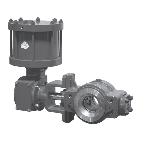
Figure 1
6 Inch 590 with DFRP-112
P-590M0620A
Website: www.dynafl o.com
21
21
21
24
26
28
30
30
30
32
33
35
35
35
36
37
38
40
41
48
1
Advertisement
Table of Contents

Related Manuals for Dyna-Flo 590


Summary of Contents for Dyna-Flo 590
-
Page 1: Table Of Contents
Model 590 Control Valve Operation, Parts, and Instruction Manual Figure 1 6 Inch 590 with DFRP-112 TABLE OF CONTENTS General Assembly Scope Stud Installation Safety Caution Ball and Shaft Assembly Specifi cations Valve Ball Centering Unpacking Live Loaded Packing Installation... -
Page 2: General
Operation, Parts, and Instruction Manual NOTICE These instructions are meant to be used with the Dyna-Flo 590 Technical Bulletin as they refer to Figures and Tables therein. If you do not have the Technical Bulletin, contact Dyna-Flo immediately, or visit www.dynafl... -
Page 3: Specifications
Table 1 See Parts section of manual for material listings. Contact your Model 590 Available Valve Size and ASME Rating Dyna-Flo sales offi ce for more information and other options. Valve Size Inch ASME Rating Flow Direction (Refer to Figures 50, 51 & 52) Single Seal Confi... -
Page 4: Unpacking
Model 590 Control Valve Operation, Parts, and Instruction Manual UNPACKING VALVE FROM SHIPPING CONTAINER Figure 2 Suggested Lifting Strap Placement Special Tools Required: • Properly Rated Lifting Straps (2 – 4 Straps). Refer to Table 2 for valve weights. LIFTING STRAP •... -
Page 5: Air Piping
KEY 51 - FLANGE STUDS KEY 53 - LONG CAP SCREWS KEY 52 - SHORT CAP SCREWS Figure 3 Line Bolt Placement Example (10 Inch 590 Shown) Refer to Figure 4 for an alternative view INSTALLATION (Continued) AIR PIPING WARNING: Property damage, environmental harm, and personal injury can result from the use of supply gas other than clean, non-corrosive, oil and moisture free air. -
Page 6: Seal Carrier Torque Requirements - Table
Model 590 Control Valve Operation, Parts, and Instruction Manual FLOW FLOW Figure 4 Valve Dimensions and Line Bolting P-590M0620A Dyna-Flo Control Valve Services Ltd. Phone: 780 4000 Toll Free: 1 2356 Fax: 780 4035 Website: www.dynafl o.com • • •... - Page 7 Model 590 Control Valve Operation, Parts, and Instruction Manual Table 3 Model 590 Valve Dimensions - Flange Bolting - Class 600 Inch Dimensional Reference Valve Size QTY. QTY. QTY. QTY. QTY. QTY. 4” 13.50 14.50 7/8 - 9 6” 4.63 4.63...
-
Page 8: Periodic Inspection
Model 590 Control Valve Operation, Parts, and Instruction Manual PERIODIC INSPECTION MAINTENANCE Special Equipment Required: NOTE: Shaft seals or live loaded packing and ball seals (Key 30) should all be inspected frequently for leaks, wear and • Bypass or block valves. -
Page 9: Shaft Seal Maintenance
Model 590 Control Valve Operation, Parts, and Instruction Manual MAINTENANCE (Continued) LIVE LOADED PACKING MAINTENANCE (Continued) NOTE: Spring washers (Key 43) function correctly when their target load (85% of their maximum defl ection/compression) is achieved. Tighten the packing fl ange nuts (Key 38) evenly in an alternating pattern keeping the packing fl... - Page 10 Model 590 Control Valve Operation, Parts, and Instruction Manual Figure 6.1 DIRECTION OF INTERNAL PRESSURE Figure 6 Follower Shaft Seal (Outboard Seal) Maintenance Diagram Reassembly (Refer to Figure 6) MAINTENANCE (Continued) Lubricate the backup ring (Key 8) with Lubriplate No. 105 ®...
-
Page 11: Ball Seal Maintenance
Model 590 Control Valve Operation, Parts, and Instruction Manual MAINTENANCE (Continued) BALL SEAL MAINTENANCE Before You Begin: • Read Safety Caution (Page 2). • Refer to Maintenance Notes (Page 8). Disassembly (Refer to Figure 8) If the valve is still in-line, make sure that the valve is in the OPEN position before it is removed from the pipe line. - Page 12 Model 590 Control Valve Operation, Parts, and Instruction Manual Figure 8 Ball Seal Maintenance Diagram Figure 9 Actuator Removal Example Figure 9.1 BLOCK BLOCK P-590M0620A Dyna-Flo Control Valve Services Ltd. Phone: 780 4000 Toll Free: 1 2356 Fax: 780 4035 Website: www.dynafl...
-
Page 13: Actuator Removal
Model 590 Control Valve Operation, Parts, and Instruction Manual ACTUATOR REMOVAL DISASSEMBLY NOTE: Actuator removal does not require that the valve be Before You Begin: removed from the pipeline. • Read Safety Caution (Page 2). • Use safe work practices and lock out procedures. - Page 14 Model 590 Control Valve Operation, Parts, and Instruction Manual Figure 10 Typical Single Seal Valve Disassembly Figure 11 Typical Dual Seal Valve Disassembly SPRING PACK ASSEMBLY Figure 12 Outboard Live Loaded Packing Disassembly P-590M0620A Dyna-Flo Control Valve Services Ltd. Phone: 780...
-
Page 15: Outboard Live Loaded Packing Removal
Model 590 Control Valve Operation, Parts, and Instruction Manual DISASSEMBLY (Continued) BODY OUTLET / SEAL PROTECTOR RING REMOVAL (Continued) For Dual Seal Construction (Refer to Figure 11) A Remove the adapter ring cap screws (Key 32). B Remove the adapter ring (Key 36). -
Page 16: Outboard Shaft Seal Removal
Model 590 Control Valve Operation, Parts, and Instruction Manual OUTBOARD SHAFT DISASSEMBLY (FOLLOWER SHAFT) Before You Begin: DISASSEMBLY (Continued) • Have the inlet side of the valve facing up on work surface. OUTBOARD SHAFT SEAL REMOVAL • Place valve in the OPEN position. - Page 17 Model 590 Control Valve Operation, Parts, and Instruction Manual Figure 16 Outboard (Follower) Shaft Disassembly (Steps 2 - 3) DISASSEMBLY (Continued) OUTBOARD SHAFT DISASSEMBLY (FOLLOWER SHAFT) (Continued) Remove the split ring (Key 19). NOTE: Split ring is two pieces. Temporarily support the ball (Key 2) and remove the follower shaft (Key 21).
-
Page 18: Inboard Live Loaded Packing Removal
Model 590 Control Valve Operation, Parts, and Instruction Manual DISASSEMBLY (Continued) LIVE LOADED PACKING REMOVAL INBOARD (DRIVE SHAFT) SIDE Disassembly Steps: Remove the packing nuts (Key 38) and the packing fl ange (Key 41). Remove the spring pack assembly (Keys 42, 43, 44). -
Page 19: Inboard Shaft Seal Removal
Model 590 Control Valve Operation, Parts, and Instruction Manual DISASSEMBLY (Continued) INBOARD SHAFT SEAL REMOVAL (DRIVE SHAFT) Disassembly Steps: With the ball (Key 2) supported, remove inboard seal carrier nuts (Key 3). Refer to Figure 21. Remove the inboard seal carrier (Key 5). NOTE: The seal carrier o-ring (Key 7) may stick to the seal carrier and get removed at the same time, remove the o-ring after. - Page 20 Model 590 Control Valve Operation, Parts, and Instruction Manual SHAFT RETAINER REMOVAL TOOL INBOARD (DRIVE) SHAFT ASSEMBLY (SEE FIGURE 23) BALL SUPPORT POST Figure 22 Inboard (Drive) Shaft Disassembly DISASSEMBLY (Continued) INBOARD SHAFT DISASSEMBLY (Continued) For Shaft Seal Assemblies Only: Remove the backup ring (Key 8), seal ring (Key 9), and spacer (Key 10) from the drive shaft (Key 17).
-
Page 21: Assembly
Model 590 Control Valve Operation, Parts, and Instruction Manual ASSEMBLY Apply Permatex Nickel Anti-Seize (Key A) to both faces of ® the thrust washer (Key 13) and to the outside surface of Before You Begin: the bushing (Key 12) and install them (this will need to be •... - Page 22 Model 590 Control Valve Operation, Parts, and Instruction Manual ASSEMBLY (Continued) BALL AND SHAFT ASSEMBLY (Continued) Place the valve body (outlet side up) on blocks (refer to Figure 27 for block placement) on a fl at work surface that can support the full assembled valve weight.
- Page 23 Model 590 Control Valve Operation, Parts, and Instruction Manual OUTLET SIDE INLET SIDE BLOCK BLOCK BLOCK BLOCK Figure 27 Support Block Placement (Step 6) SEE NOTE Align Index Marks NOTE: For rare circumstances when the alignment mark is not visible (on the 10 inch ball for example), move the ball into the fully open position inside the valve body and insert the tapered polygon end connection of the shaft into the ball so that the alignment mark of the shaft polygon is placed into the corner of the ball polygon that faces the open end of the valve ball (parallel to the fl...
-
Page 24: Valve Ball Centering
Model 590 Control Valve Operation, Parts, and Instruction Manual OUTBOARD (FOLLOWER) SHAFT ASSEMBLY (SEE FIGURE 24) Figure 30 Outboard (Follower) Shaft Installation (Steps 14 - 15) VALVE BALL AND SHAFT VIEW ROTATED 90° FOR CLARITY DO NOT ROTATE VALVE BALL DURING INSTALLATION. - Page 25 Model 590 Control Valve Operation, Parts, and Instruction Manual ASSEMBLY (Continued) VALVE BALL CENTERING (Continued) For Shaft Seal Assemblies: A Temporarily install the spacer (Key 14). B Install the backup ring (Key 8) and seal ring (Key 9) into the seal carrier (Key 6) (Refer to Figure 37 for seal ring orientation).
-
Page 26: Live Loaded Packing Installation
Model 590 Control Valve Operation, Parts, and Instruction Manual ASSEMBLY (Continued) LIVE LOADED PACKING INSTALLATION Outboard (Follower Shaft Side) Once the valve ball (Key 2) has been properly centered, remove the outboard packing box (Key 49). Apply Dow Corning Molykote 111 (Key B) to the packing box o-ring ®... - Page 27 Model 590 Control Valve Operation, Parts, and Instruction Manual ASSEMBLY (Continued) LIVE LOADED PACKING INSTALLATION (Continued) Install the live loaded packing follower (Key 45). Apply Permatex Nickel Anti-Seize (Key A) to the top threads of ® the packing studs (Key 39).
-
Page 28: Shaft Seal Installation
Model 590 Control Valve Operation, Parts, and Instruction Manual ASSEMBLY (Continued) 20 Install the spring washers (Key 43) on to the inboard packing follower (Key 44) in the appropriate order and LIVE LOADED PACKING INSTALLATION (Continued) orientation shown in Figures 44, 45, 46, 47. Secure the 12 Install and tighten the nuts (Key 3) or cap screws (Key spring washers in place using the packing fl... - Page 29 Model 590 Control Valve Operation, Parts, and Instruction Manual SEE FIGURE 37 Figure 38 Shaft Seal Installation Diagram ASSEMBLY (Continued) Once the valve shaft (Key 17) and ball (Key 2) are able to rotate freely while the seal carrier (Key 5) is tightened in SHAFT SEAL INSTALLATION (Continued) place.
-
Page 30: Ball Seal Installation
Model 590 Control Valve Operation, Parts, and Instruction Manual ASSEMBLY (Continued) For Dual Seal Valve Construction: BALL SEAL INSTALLATION NOTE: For Single Seal Construction proceed to BODY OUTLET INSTALLATION below. Before You Begin: • After installing the fi rst ball seal (Steps 1 – 8), fl ip the •... - Page 31 Model 590 Control Valve Operation, Parts, and Instruction Manual Figure 39 Typical Single Seal Valve Disassembly Figure 40 Typical Dual Seal Valve Disassembly AFTER 3 SHIMS (KEY 31) HAVE BEEN REMOVED Figure 41 Proper Ball Seal and Shim Installation (Steps 2 to 5) P-590M0620A Dyna-Flo Control Valve Services Ltd.
-
Page 32: Actuator Mounting
Model 590 Control Valve Operation, Parts, and Instruction Manual BALL AND FLOW RING CLEARANCE ASSEMBLY (Continued) FLOW RING INSTALLATION (Continued) Carefully install the fl ow ring (Key 28). The fl ow ring has threaded holes for lifting hooks, utilize lifting hooks to lower the part into position if possible. -
Page 33: Live Loaded Packing Diagrams
Model 590 Control Valve Operation, Parts, and Instruction Manual Figure 44 6 Inch Valve Inboard and Outboard Live Loaded Packing Arrangement Figure 45 4 & 8 Inch Valve Inboard and Outboard Live Loaded Packing Arrangement P-590M0620A Dyna-Flo Control Valve Services Ltd. - Page 34 Model 590 Control Valve Operation, Parts, and Instruction Manual Figure 46 10 & 16 Inch Valve Inboard and Outboard Live Loaded Packing Arrangement Figure 47 12 Inch Valve Inboard and Outboard Live Loaded Packing Arrangement P-590M0620A Dyna-Flo Control Valve Services Ltd.
-
Page 35: Travel Adjustment
Model 590 Control Valve Operation, Parts, and Instruction Manual TRAVEL ADJUSTMENT For Assemblies Removed From Pipeline: Rotate the ball (Key 2) to the fully open position. The ball is Adjustments can be made to actuator travel with the valve full open when the inside surface of the ball bore is square assembly either in or removed from the pipeline. -
Page 36: Ball Support Post And Retainer Removal Tool
Model 590 Control Valve Operation, Parts, and Instruction Manual Z1/Z2 Figure 48 Ball Support Post and Shaft Retainer Removal Tool Construction Dimensions Table 8 Ball Support Post and Shaft Retainer Removal Tool Dimensions Inch (mm) Valve Size 1.615 1.245 0.342 (41.02) - Page 37 Model 590 Control Valve Operation, Parts, and Instruction Manual Figure 49 Actuator / Valve Position Chart ACTUATOR VALVE OPEN (diagrams shown using DFRP model actuators) STYLE A PUSH DOWN TO CLOSE CLOSE (PDTC) FLOW ACTUATOR POSITIONS CLOSE STYLE B PUSH DOWN TO OPEN...
-
Page 38: Live Loaded Packing Single Seal Cross
Model 590 Control Valve Operation, Parts, and Instruction Manual INBOARD SIDE Figure 50 Typical Live Loaded Packing Single Seal Valve Assembly INLET FRONT VIEW OUTBOARD SIDE P-590M0620A Dyna-Flo Control Valve Services Ltd. Phone: 780 4000 Toll Free: 1 2356 Fax: 780 4035 Website: www.dynafl... - Page 39 Model 590 Control Valve Operation, Parts, and Instruction Manual INBOARD SIDE Figure 51 Typical Shaft Seal Single Seal Valve Assembly INLET FRONT VIEW 24 23 OUTBOARD SIDE P-590M0620A Dyna-Flo Control Valve Services Ltd. Phone: 780 4000 Toll Free: 1 2356...
- Page 40 Model 590 Control Valve Operation, Parts, and Instruction Manual INBOARD SIDE Figure 52 Typical Dual Seal Valve Assembly INLET FRONT VIEW 24 23 OUTBOARD SIDE P-590M0620A Dyna-Flo Control Valve Services Ltd. Phone: 780 4000 Toll Free: 1 2356 Fax: 780 4035 Website: www.dynafl...
-
Page 41: Parts
Model 590 Control Valve Operation, Parts, and Instruction Manual Parts Description Part Number Description Part Number Outboard Seal Carrier, S31600 4 Inch 28A2514X03D Body 6 Inch 38A2539X03D If you need a body as a replacement part, order by 8 Inch... - Page 42 Model 590 Control Valve Operation, Parts, and Instruction Manual Parts (Continued) Description Part Number Drive Shaft, Continued Description Part Number 12 Inch 38A2636X02D Bushing, S31600/S31603 Dual Grade / CPTFE, 16 Inch 38A8604X02D 2 Required Pin, Follower Shaft, 4 Inch 18A2520X04D...
- Page 43 Model 590 Control Valve Operation, Parts, and Instruction Manual Parts (Continued) Description Part Number 12 Inch (4 Required) 10A1058X08D Description Part Number 16 Inch (4 Required) 10A1058X08D Indicator Scale, Continued Body Outlet Contact Dyna-Flo 12 Inch 38A5034X01D Gasket, Body Outlet / Adapter Ring,...
- Page 44 Parts Ordering Description Part Number Whenever corresponding with Dyna-Flo Stud, Live Loaded Packing Flange (Continued) about a 590 Control Valve, refer to the B8M, 4 Required nameplate for the serial number of the 10 Inch STB8M-078-400 unit. Please order by the complete part...
- Page 45 Model 590 Control Valve Operation, Parts, and Instruction Manual Table 9 Live Loaded Packing Retro-Fit Kit Valve Size Part Number 4 Inch R590XLR040D 6 Inch R590XLR060D 8 Inch R590XLR080D 10 Inch R590XLR100D 12 Inch R590XLR120D 16 Inch R590XLR160D Kit Includes...
- Page 46 Model 590 Control Valve Operation, Parts, and Instruction Manual Table 10 Live Loaded Repair Kit Size Part Number 4 Inch R590XL0040D 6 Inch R590XL0060D 8 Inch R590XL0080D 10 Inch R590XL0100D 12 Inch R590XL0120D 16 Inch R590XL0160D Kit Includes Description 7 (Quantity 2)
- Page 47 Model 590 Control Valve Operation, Parts, and Instruction Manual This page left intentionally blank. P-590M0620A Dyna-Flo Control Valve Services Ltd. Phone: 780 4000 Toll Free: 1 2356 Fax: 780 4035 Website: www.dynafl o.com • • • • • • •...
-
Page 48: Model Builder
Model 590 Control Valve MODEL NUMBERING SYSTEM S A M P L E PA R T N U M B E R : 590- 8 - C L S - P N VALVE SIZE 4 INCH 6 INCH 8 INCH...
Need help?
Do you have a question about the 590 and is the answer not in the manual?
Questions and answers