Table of Contents
Advertisement
Quick Links
This user's guide describes the characteristics, operation, and use of the TPS63070EVM evaluation
module (EVM). The TPS63070EVM-693 is designed to help the users easily evaluate and test the
operation and functionality of the TPS63070 Buck-Boost Converter. The TPS63070EVM-693 uses the
TPS63070 adjustable version, the output voltage is set to 3.3V/5.0V.The user can select the output
voltage with the VSEL pin. The EVM operates from 2.0V to 16V input voltage. Output currents can go up
to 2A in buck mode and boost mode. This document includes setup instructions for the hardware, a
schematic diagram, a bill of materials (BOM), and printed-circuit board (PCB) layout drawings for the
evaluation module. Throughout this document, the abbreviations EVM, TPS63070EVM-693, and the term
evaluation module are synonymous with the TPS63070, unless otherwise noted.
...................................................................................................................
1
1.1
1.2
1.3
..........................................................................................................................
2
2.1
2.2
3
3.1
4
4.1
4.2
1
Introduction
The Texas Instruments TPS63070 is a highly efficient, single-inductor, internally compensated, buck-boost
converter in a 15-pin, 2.5-mm × 3-mm HotRod package. Both fixed and adjustable output voltage units are
available.
1.1
Background
The TPS63070EVM-693 uses the TPS63070 adjustable-output voltage version of the integrated circuit
(IC) and is set to a 3.3V / 5.0V output. The fixed-output version(s) can be evaluated on this EVM with
minor modification as stated in section titled, Fixed Output Operation. The EVM operates with an input
voltage between 2.0 V and 16 V.
SLVUAO5A - June 2016 - Revised March, 2018
Submit Documentation Feedback
..........................................................................................................
.........................................................................................
.........................................................................................................
.................................................................................................................
.................................................................................................................
................................................................................................................
............................................................................................
............................................................................................................
......................................................................................................
Copyright © 2016-2018, Texas Instruments Incorporated
SLVUAO5A - June 2016 - Revised March, 2018
TPS63070EVM-693
Contents
..............................................................
User's Guide
1
1
2
2
2
2
3
4
4
6
6
7
1
TPS63070EVM-693
Advertisement
Table of Contents

Related Manuals for Texas Instruments TPS63070EVM-693


Summary of Contents for Texas Instruments TPS63070EVM-693
-
Page 1: Table Of Contents
This user’s guide describes the characteristics, operation, and use of the TPS63070EVM evaluation module (EVM). The TPS63070EVM-693 is designed to help the users easily evaluate and test the operation and functionality of the TPS63070 Buck-Boost Converter. The TPS63070EVM-693 uses the TPS63070 adjustable version, the output voltage is set to 3.3V/5.0V.The user can select the output... -
Page 2: Performance Specification
Introduction www.ti.com Performance Specification Table 1 provides a summary of the TPS63070EVM-693 performance specifications. All specifications are given for an ambient temperature of 25°C. Table 1. Performance Specification Summary Specification Test Conditions Unit Input voltage Output voltage Output current during operation VIN ≥ 4.5V 2000 during operation VOUT≥4.5 and boost factor... -
Page 3: Setup
J1, pins 5 and 6; connect a load with the positive lead to J2, pins 1 and 2 and the negative lead to J2, pins 5 and 6; short EN and HIGH (pins 2 and 3) of JP1 with a shorting jumper. SLVUAO5A – June 2016 – Revised March, 2018 TPS63070EVM-693 Submit Documentation Feedback Copyright © 2016–2018, Texas Instruments Incorporated... -
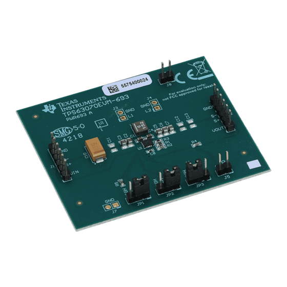
Page 4: Board Layout
Board Layout www.ti.com Board Layout This section provides the TPS63070EVM-693 board layout and illustrations. Layout Figure 1 through Figure 3 show the board layout for the TPS63070EVM-693 PCB. Figure 1. Assembly Layer TPS63070EVM-693 SLVUAO5A – June 2016 – Revised March, 2018 Submit Documentation Feedback Copyright ©... - Page 5 Board Layout www.ti.com Figure 2. Top Layer Routing Figure 3. Bottom Layer Routing SLVUAO5A – June 2016 – Revised March, 2018 TPS63070EVM-693 Submit Documentation Feedback Copyright © 2016–2018, Texas Instruments Incorporated...
-
Page 6: Schematic And Bill Of Materials
Schematic and Bill of Materials www.ti.com Schematic and Bill of Materials This section provides the TPS63070EVM-693 schematic and bill of materials. Schematic 1.5µH VOUT VOUT VOUT 2V - 16V 2.5V - 9V VOUT 100k 470k VSEL 68µF 221k 10µF 10µF 10µF... -
Page 7: Bill Of Materials
Schematic and Bill of Materials www.ti.com Bill of Materials Table 2. TPS63070EVM-693 Bill of Materials Count RefDes Value Description Size Part Number C1,C4 10uF CAP, CERM, 10 µF, 25 V, +/- 20%, X5R, 0603 GRM188R61E106MA73 Murata C2,C3 10uF CAP, CERM, 10 µF, 25 V, +/- 20%, X7S, 0805... - Page 8 STANDARD TERMS FOR EVALUATION MODULES Delivery: TI delivers TI evaluation boards, kits, or modules, including any accompanying demonstration software, components, and/or documentation which may be provided together or separately (collectively, an “EVM” or “EVMs”) to the User (“User”) in accordance with the terms set forth herein.
- Page 9 FCC Interference Statement for Class B EVM devices NOTE: This equipment has been tested and found to comply with the limits for a Class B digital device, pursuant to part 15 of the FCC Rules. These limits are designed to provide reasonable protection against harmful interference in a residential installation.
- Page 10 【無線電波を送信する製品の開発キットをお使いになる際の注意事項】 開発キットの中には技術基準適合証明を受けて いないものがあります。 技術適合証明を受けていないもののご使用に際しては、電波法遵守のため、以下のいずれかの 措置を取っていただく必要がありますのでご注意ください。 1. 電波法施行規則第6条第1項第1号に基づく平成18年3月28日総務省告示第173号で定められた電波暗室等の試験設備でご使用 いただく。 2. 実験局の免許を取得後ご使用いただく。 3. 技術基準適合証明を取得後ご使用いただく。 なお、本製品は、上記の「ご使用にあたっての注意」を譲渡先、移転先に通知しない限り、譲渡、移転できないものとします。 上記を遵守頂けない場合は、電波法の罰則が適用される可能性があることをご留意ください。 日本テキサス・イ ンスツルメンツ株式会社 東京都新宿区西新宿6丁目24番1号 西新宿三井ビル 3.3.3 Notice for EVMs for Power Line Communication: Please see http://www.tij.co.jp/lsds/ti_ja/general/eStore/notice_02.page 電力線搬送波通信についての開発キットをお使いになる際の注意事項については、次のところをご覧ください。http:/ /www.tij.co.jp/lsds/ti_ja/general/eStore/notice_02.page 3.4 European Union 3.4.1 For EVMs subject to EU Directive 2014/30/EU (Electromagnetic Compatibility Directive): This is a class A product intended for use in environments other than domestic environments that are connected to a low-voltage power-supply network that supplies buildings used for domestic purposes.
- Page 11 Notwithstanding the foregoing, any judgment may be enforced in any United States or foreign court, and TI may seek injunctive relief in any United States or foreign court. Mailing Address: Texas Instruments, Post Office Box 655303, Dallas, Texas 75265 Copyright © 2018, Texas Instruments Incorporated...
- Page 12 IMPORTANT NOTICE FOR TI DESIGN INFORMATION AND RESOURCES Texas Instruments Incorporated (‘TI”) technical, application or other design advice, services or information, including, but not limited to, reference designs and materials relating to evaluation modules, (collectively, “TI Resources”) are intended to assist designers who are developing applications that incorporate TI products;...
Need help?
Do you have a question about the TPS63070EVM-693 and is the answer not in the manual?
Questions and answers