Table of Contents
Advertisement
Quick Links
This document presents the information required to operate the TPS65265 PMIC as well as the support
documentation including schematic, printed-circuit board (PCB) layout, hardware setup, and bill of
materials.
...................................................................................................................
1
.....................................................................................................................
2
3
4
4.1
5
Power-Up Procedure
6
Bill of Materials
1
TPS65265EVM-705 Schematic
2
Component Placement (Top Layer)
3
Board Layout (Top Layer)
4
Board Layout (Second Layer)
5
Board Layout (Third Layer)
6
Board Layout (Bottom Layer)
7
1
Summary of Performance
2
.......................................................................................................................
3
4
5
SLVUAK9 - December 2015
Submit Documentation Feedback
TPS65265EVM-705 Evaluation Module
.................................................................................................................
..............................................................................................
........................................................................................................
...............................................................................................................
............................................................................................
.......................................................................................
..................................................................................................
..............................................................................................
.................................................................................................
..............................................................................................
..................................................................................................
....................................................................................................
...........................................................................................................
......................................................................................
Copyright © 2015, Texas Instruments Incorporated
Contents
....................................................................
List of Figures
.....................................................
List of Tables
TPS65265EVM-705 Evaluation Module
User's Guide
SLVUAK9 - December 2015
2
2
3
6
6
7
8
2
3
3
4
4
5
6
2
6
7
7
8
1
Advertisement
Table of Contents

Related Manuals for Texas Instruments TPS65265EVM-705


Summary of Contents for Texas Instruments TPS65265EVM-705
-
Page 1: Table Of Contents
....................Board Layout (Top Layer) ....................Board Layout (Second Layer) ....................Board Layout (Third Layer) ....................Board Layout (Bottom Layer) ............. TPS65265EVM-705 Header Description and Jumper Placement List of Tables ....................Summary of Performance ....................Input/Output Connection ........................Jumpers ...................... -
Page 2: Background
Please contact the TI Field Applications Group for advice on these matters. Schematic Figure 1 illustrates the TPS65265EVM-705 EVM schematic. 0.047uF VOUT1 1.2V 5A VOUT1 VIN 12V 2.2uH... -
Page 3: Board Layout
Board Layout www.ti.com Board Layout Figure 2 through Figure 6 illustrate the TPS65265EVM-705 PCB layout. Figure 2. Component Placement (Top Layer) Figure 3. Board Layout (Top Layer) SLVUAK9 – December 2015 TPS65265EVM-705 Evaluation Module Submit Documentation Feedback Copyright © 2015, Texas Instruments Incorporated... - Page 4 Board Layout www.ti.com Figure 4. Board Layout (Second Layer) Figure 5. Board Layout (Third Layer) TPS65265EVM-705 Evaluation Module SLVUAK9 – December 2015 Submit Documentation Feedback Copyright © 2015, Texas Instruments Incorporated...
- Page 5 Board Layout www.ti.com Figure 6. Board Layout (Bottom Layer) SLVUAK9 – December 2015 TPS65265EVM-705 Evaluation Module Submit Documentation Feedback Copyright © 2015, Texas Instruments Incorporated...
-
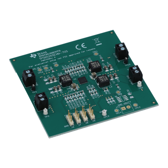
Page 6: Bench Test Setup Conditions
Bench Test Setup Conditions Header Description and Jumper Placement Figure 7 shows the jumper and pin placement on the TPS65265EVM-705 board. Figure 7. TPS65265EVM-705 Header Description and Jumper Placement Test points: (A) LX of VOUT1 (B) LX of VOUT2... -
Page 7: Jumpers
High Buck2→buck1→buck3 Buck3→buck1→buck2 High Buck2→buck3→buck1 Buck1→buck3→buck2 High High High Buck1→buck3→buck2 Buck2→buck3→buck1 High High Buck3→buck1→buck2 Buck2→buck1→buck3 High High Buck3→buck2→buck1 Buck1→buck2→buck3 High/Low Reserved Reserved Reserved SLVUAK9 – December 2015 TPS65265EVM-705 Evaluation Module Submit Documentation Feedback Copyright © 2015, Texas Instruments Incorporated... -
Page 8: Tps65265Evm-705 Bill Of Materials
Bill of Materials www.ti.com Bill of Materials Table 5 lists the TPS65265EVM-705 BOM. Table 5. TPS65265EVM-705 Bill of Materials Value Designator Footprint Manufacturer Manufacturer Part Description Number 47nF C8, C9, C17 0603 Generic CAP 47nF 50V CERAMIC X7R 0603 10nF... - Page 9 STANDARD TERMS AND CONDITIONS FOR EVALUATION MODULES Delivery: TI delivers TI evaluation boards, kits, or modules, including any accompanying demonstration software, components, or documentation (collectively, an “EVM” or “EVMs”) to the User (“User”) in accordance with the terms and conditions set forth herein. Acceptance of the EVM is expressly subject to the following terms and conditions.
- Page 10 FCC Interference Statement for Class B EVM devices NOTE: This equipment has been tested and found to comply with the limits for a Class B digital device, pursuant to part 15 of the FCC Rules. These limits are designed to provide reasonable protection against harmful interference in a residential installation.
- Page 11 【無線電波を送信する製品の開発キットをお使いになる際の注意事項】 開発キットの中には技術基準適合証明を受けて いないものがあります。 技術適合証明を受けていないもののご使用に際しては、電波法遵守のため、以下のいずれかの 措置を取っていただく必要がありますのでご注意ください。 1. 電波法施行規則第6条第1項第1号に基づく平成18年3月28日総務省告示第173号で定められた電波暗室等の試験設備でご使用 いただく。 2. 実験局の免許を取得後ご使用いただく。 3. 技術基準適合証明を取得後ご使用いただく。 なお、本製品は、上記の「ご使用にあたっての注意」を譲渡先、移転先に通知しない限り、譲渡、移転できないものとします。 上記を遵守頂けない場合は、電波法の罰則が適用される可能性があることをご留意ください。 日本テキサス・イ ンスツルメンツ株式会社 東京都新宿区西新宿6丁目24番1号 西新宿三井ビル 3.3.3 Notice for EVMs for Power Line Communication: Please see http://www.tij.co.jp/lsds/ti_ja/general/eStore/notice_02.page 電力線搬送波通信についての開発キットをお使いになる際の注意事項については、次のところをご覧くださ い。http://www.tij.co.jp/lsds/ti_ja/general/eStore/notice_02.page SPACER EVM Use Restrictions and Warnings: 4.1 EVMS ARE NOT FOR USE IN FUNCTIONAL SAFETY AND/OR SAFETY CRITICAL EVALUATIONS, INCLUDING BUT NOT LIMITED TO EVALUATIONS OF LIFE SUPPORT APPLICATIONS.
- Page 12 Notwithstanding the foregoing, any judgment may be enforced in any United States or foreign court, and TI may seek injunctive relief in any United States or foreign court. Mailing Address: Texas Instruments, Post Office Box 655303, Dallas, Texas 75265 Copyright © 2015, Texas Instruments Incorporated...
- Page 13 IMPORTANT NOTICE Texas Instruments Incorporated and its subsidiaries (TI) reserve the right to make corrections, enhancements, improvements and other changes to its semiconductor products and services per JESD46, latest issue, and to discontinue any product or service per JESD48, latest issue.
Need help?
Do you have a question about the TPS65265EVM-705 and is the answer not in the manual?
Questions and answers