Table of Contents
Advertisement
Quick Links
TPS65295EVM-079, 4.5-V to 18-V
This user's guide contains information for the TPS65295 as well as support documentation for the
TPS65295EVM-079 evaluation module. Included are the performance specifications, schematic, and the
...................................................................................................................
1
2
3
3.1
3.2
3.3
3.4
3.5
3.6
3.7
4
5
5.1
5.2
Schematic
5.3
List of Materials
5.4
1
Headers Description and Jumper Placement
2
3
4
5
6
TPS65295EVM-079 Power Up Relative to SLP_S4
7
TPS65295EVM-079 Power Down Relative to SLP_S4
8
.....................................................................................................................
9
10
11
12
13
14
15
1
2
.....................................................................................
.....................................................................................................
..........................................................................................
.................................................................................................
.........................................................................................
..............................................................................................
............................................................................................................
.........................................................................................................
.................................................................................................................
.......................................................................................................
..........................................................................................................
....................................................................................................
..........................................................................................................
= 8 A
OUT
= 1 A
OUT
................................................................................................................
..................................................................................................................
................................................................................................................
................................................................................................................
.........................................................................................
.....................................................................................
..........................................................................................
Copyright © 2019, Texas Instruments Incorporated
, complete DDR4 power
IN
solution evaluation module
Contents
..................................................................
...........................................................
List of Figures
............................................................................
...........................................................................
..............................................................................
....................................................................
.................................................................
List of Tables
.............................................................................
...........................................................
TPS65295EVM-079, 4.5-V to 18-V
User's Guide
SLUUC02 - February 2019
.......................................
........................................
, complete DDR4 power solution
IN
evaluation module
2
2
3
3
4
5
5
6
7
7
8
11
11
13
14
14
3
5
5
6
6
7
7
8
9
9
10
10
11
12
13
2
2
1
Advertisement
Table of Contents

Related Manuals for Texas Instruments TPS65295EVM-079


Summary of Contents for Texas Instruments TPS65295EVM-079
-
Page 1: Table Of Contents
TPS65295EVM-079, 4.5-V to 18-V , complete DDR4 power solution evaluation module This user's guide contains information for the TPS65295 as well as support documentation for the TPS65295EVM-079 evaluation module. Included are the performance specifications, schematic, and the List of Materials. Contents ........................ -
Page 2: Introduction
A summary of the TPS65295EVM-079 performance specifications is provided in Table 2. The TPS65295EVM-079 is designed and tested for VIN = 4.5 V to 18V. The Junction temperature is 25°C for all measurements, unless otherwise noted. Table 2. TPS65295EVM-079 Performance Specifications Summary... -
Page 3: Test Setup And Results
Test Setup and Results www.ti.com Test Setup and Results This section describes how to properly connect, set up, and use the TPS65295EVM-079. The section also includes test results typical for the evaluation modules. Headers Description and Jumper Placement. Figure 1. Headers Description and Jumper Placement SLUUC02 –... -
Page 4: Input/Output Connections
Test Setup and Results www.ti.com Input/Output Connections The TPS65295EVM-079 is provided with input/output connectors and test points as shown in Table 4 Jumpers description shown in Table 3. A power supply capable of supplying greater than 8A must be connected to J1 through a pair of 20-AWG wires or better. The load must be connected to J2 through a pair of 20-AWG wires or better. -
Page 5: Start-Up Procedure
J4 and J2 first, and then apply the J2-2 for VCC_5V. 5. Check the outputs. Load Transient Response The TPS65295EVM-079 VDDQ and VPP response to load transient is shown in Figure 1 Figure The current steps and slew rates are indicated in the figures. Total peak-to-peak voltage variation is as shown. -
Page 6: Output Voltage Ripple
Test Setup and Results www.ti.com Output Voltage Ripple The TPS65295EVM-079 output voltage ripple is shown in Figure 4, and Figure 5. The output currents are as indicated. VDDQ ILoading Figure 4. TPS65295EVM-079 VDDQ Ripple, I = 8 A ILoading Figure 5. TPS65295EVM-079 VPP Ripple, I = 1 A TPS65295EVM-079, 4.5-V to 18-V... -
Page 7: Power-Up
Test Setup and Results www.ti.com Power-Up The TPS65295EVM-079 power up waveform relative to SLP_S4 is shown in Figure SLP_S4 VDDQ VTTREF Figure 6. TPS65295EVM-079 Power Up Relative to SLP_S4 Power-Down The TPS65295EVM-079 power down waveform relative to SLP_S4 is shown in... -
Page 8: Board Layout
This section provides a description of the TPS65295EVM-079 board layout and layer illustrations. The board layout for the TPS65295EVM-079 is shown in Figure 9 ~ Figure 12. The top and bottom are 2-oz. copper and internal layers are 1-oz. copper. -
Page 9: Top Layer
Board Layout www.ti.com Figure 9. Top Layer Figure 10. Inner1 Layer SLUUC02 – February 2019 TPS65295EVM-079, 4.5-V to 18-V , complete DDR4 power solution evaluation module Submit Documentation Feedback Copyright © 2019, Texas Instruments Incorporated... -
Page 10: Inner2 Layer
Board Layout www.ti.com Figure 11. Inner2 Layer Figure 12. Bottom Layer TPS65295EVM-079, 4.5-V to 18-V , complete DDR4 power solution SLUUC02 – February 2019 evaluation module Submit Documentation Feedback Copyright © 2019, Texas Instruments Incorporated... -
Page 11: Board Profile, Schematic, List Of Materials And Reference
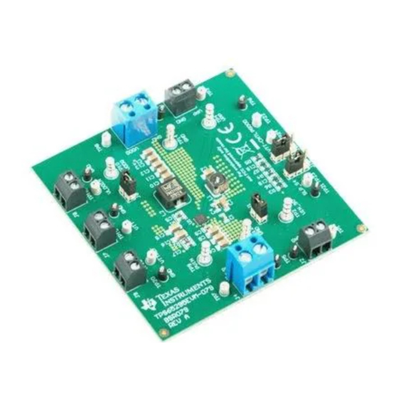
Board Profile, Schematic, List of Materials and Reference www.ti.com Board Profile, Schematic, List of Materials and Reference Board Profile Figure 13 is the top view for the TPS65295EVM-079. Figure 13. Top View of TPS65295EVM-079 SLUUC02 – February 2019 TPS65295EVM-079, 4.5-V to 18-V , complete DDR4 power solution... -
Page 12: Bottom View Of Tps65295Evm-079
Board Profile, Schematic, List of Materials and Reference www.ti.com Figure 14 is the bottom view for the TPS65295EVM-079. Figure 14. Bottom View of TPS65295EVM-079 TPS65295EVM-079, 4.5-V to 18-V , complete DDR4 power solution SLUUC02 – February 2019 evaluation module Submit Documentation Feedback... -
Page 13: Tps65295Evm-079 Schematic
Board Profile, Schematic, List of Materials and Reference www.ti.com Schematic Figure 15 is the schematic for the TPS65295EVM-079. Figure 15. TPS65295EVM-079 Schematic SLUUC02 – February 2019 TPS65295EVM-079, 4.5-V to 18-V , complete DDR4 power solution evaluation module Submit Documentation Feedback... -
Page 14: List Of Materials
Board Profile, Schematic, List of Materials and Reference www.ti.com List of Materials Table 5 displays the TPS65295EVM-079 bill of materials. Table 5. List of Materials DESIGNATOR QUANTITY DESCRIPTION PART NUMBER MANUFACTURER Printed Circuit Board BSR079 Capacitor, ceramic, 1 µF, 25 V, ±10%, X7R, 0603... - Page 15 STANDARD TERMS FOR EVALUATION MODULES Delivery: TI delivers TI evaluation boards, kits, or modules, including any accompanying demonstration software, components, and/or documentation which may be provided together or separately (collectively, an “EVM” or “EVMs”) to the User (“User”) in accordance with the terms set forth herein.
- Page 16 www.ti.com Regulatory Notices: 3.1 United States 3.1.1 Notice applicable to EVMs not FCC-Approved: FCC NOTICE: This kit is designed to allow product developers to evaluate electronic components, circuitry, or software associated with the kit to determine whether to incorporate such items in a finished product and software developers to write software applications for use with the end product.
- Page 17 www.ti.com Concernant les EVMs avec antennes détachables Conformément à la réglementation d'Industrie Canada, le présent émetteur radio peut fonctionner avec une antenne d'un type et d'un gain maximal (ou inférieur) approuvé pour l'émetteur par Industrie Canada. Dans le but de réduire les risques de brouillage radioélectrique à...
- Page 18 www.ti.com EVM Use Restrictions and Warnings: 4.1 EVMS ARE NOT FOR USE IN FUNCTIONAL SAFETY AND/OR SAFETY CRITICAL EVALUATIONS, INCLUDING BUT NOT LIMITED TO EVALUATIONS OF LIFE SUPPORT APPLICATIONS. 4.2 User must read and apply the user guide and other available documentation provided by TI regarding the EVM prior to handling or using the EVM, including without limitation any warning or restriction notices.
- Page 19 Notwithstanding the foregoing, any judgment may be enforced in any United States or foreign court, and TI may seek injunctive relief in any United States or foreign court. Mailing Address: Texas Instruments, Post Office Box 655303, Dallas, Texas 75265 Copyright © 2019, Texas Instruments Incorporated...
- Page 20 TI products. TI’s provision of these resources does not expand or otherwise alter TI’s applicable warranties or warranty disclaimers for TI products. Mailing Address: Texas Instruments, Post Office Box 655303, Dallas, Texas 75265 Copyright © 2019, Texas Instruments Incorporated...
Need help?
Do you have a question about the TPS65295EVM-079 and is the answer not in the manual?
Questions and answers