Sign In
Upload
Manuals
Brands
barfield Manuals
Test Equipment
1811NG
User Manuals: barfield 1811NG Static Test Set
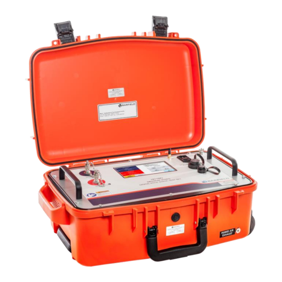
Manuals and User Guides for barfield 1811NG Static Test Set. We have
1
barfield 1811NG Static Test Set manual available for free PDF download: User Instruction Manual
barfield 1811NG User Instruction Manual (102 pages)
Pitot-Static Test Set
Brand:
barfield
| Category:
Test Equipment
| Size: 3 MB
Table of Contents
Revision Record
7
Table of Contents
8
List of Figures
10
Figure 1 Identification Label
13
Information Provided with the Test Set
13
Introduction
13
Publication Breakdown
13
Figure 2 Owner Warranty Registration Card
14
Recertification
14
Mobile Device's App Information
15
Software Update
15
Test Set Equivalent
15
Figure 3 Limited 2 Year Warranty
16
Chapter 1: General
17
Intended Use
17
Specifications
17
Table 1 Physical Characteristics
17
Table 2 Environmental
17
Table 3 Conformity
17
Table 4 Aeronautical Specifications
18
Table 5 Pressure Units Specifications
19
Table 6 Display Units
19
Instructions for Use
20
Technical Assistance
21
Chapter 2: Ratings
22
Supply Voltages
22
Connection Description
22
Environmental
22
Figure 4 Power Entry Module
22
Chapter 3: Installation
23
Assembly
23
Figure 5 Case Dimensions
23
Grounding (Earthing)
24
Figure 6 Optional Travel / Shipping Case
24
Electrical Connections
25
Ventilation / Drainage
25
Figure 7 Power Supply Cable
25
Figure 8 Do Not Obstruct Vents
25
Figure 9 Humid Air Exhaust
25
Pneumatic Pressure Connections
26
Figure 10 1811Ng Pressure Connections
26
Chapter 4: Operation
27
Operating Controls
27
Figure 11 1811Ng Front Panel
27
Positioning
28
Accessories
28
Figure 12 Instruction Manual, P/N 56-101-01178
29
Figure 13 Electrical Cable, P/N Ae9887-Nd
29
Figure 14 Hose Kit, P/N 115-00633
29
Figure 15 Antenna, P/N 126-00001
30
Figure 16 Carrying Bag, P/N 195-00021
30
Figure 17 An4 Caps with Lanyard, P/N 176-00001
30
Preparation
31
Power on Initialization
31
Figure 18 Power on Initialization Display
31
Operating Modes
32
Test Set Configuration Status Display
33
Figure 19 Default 2-Channel (Dual Ps, Pt) Mode
33
Figure 20 Optional 1-Channel (Pt Only) Mode
33
Figure 21 Test Set Configuration Information Displayed
34
User Interface Menu and Display
35
Figure 22 Display Setup Aeronautical Menu
35
Figure 23 Hold/Resume Feature Displayed
36
Figure 24 Target Value Keypad Screen
36
Figure 25 Display Setup: 4-Parameter
37
Figure 26 Display Setup: 2-Parameter Formats
37
Figure 27 Display Units - for Aeronautical Mode
38
Figure 28 Display Units - for Pressure Units Mode
38
Figure 29 Leak Testing Menu
38
Figure 30 Leak Rate Timer Results
39
Figure 31 Select Atp Leak Test Profile
40
Figure 32 Atp Leak Test - Parameter Profile Screen
41
Figure 33 Atp Leak Test Results Screen
41
Figure 34 Go to Ground Confirm Screen
42
Figure 35 Conclusion of Go to Ground
42
Figure 36 Setup 1
43
Figure 37 Altitude Correction Screen
44
Figure 38 Altitude Correction On-Aircraft
44
Figure 39 Altitude Correction Keypad
44
Figure 40 Test Set Configuration, Updated Altitude Correction
45
Figure 41 Setup 1 Control Mode(S)
45
Figure 43 Setup 2 - Selecting Limit File to Edit
46
Figure 43 Setup 2 - Edit Custom Limits
46
Figure 44 Delete Custom Limits
47
Figure 45 Backlight Adjustment
49
Test Set Operation
50
Figure 46 1811Ng Front Panel
50
Figure 47 Initialization Display
51
Test Set Leak Test
53
Figure 48 Leak Testing Menu(S)
53
Figure 49 Selecting Atp Leak Test Profile
54
Figure 50 Leak Test Profile - Parameters Screen
54
Figure 51 Leak Test Timer Screen
55
Figure 52 Leak Rate Timer, Unit Safe at Ground
56
Figure 53 Atp Leak Test
56
Figure 54 Atp Leak Test Results
57
Aircraft Testing
58
Figure 57 Unit Safe at Ground
59
Figure 56 Leak Test Results
61
Engine Pressure Ratio (Epr) Test
68
Table 7 Engine Pressure Ratio Test Table
69
Shutdown Procedure
70
Figure 57 Confirm Go to Ground
70
Figure 58 Unit Safe at Ground
70
Chapter 5: Receiving, Shipping, and Storage
72
Receiving
72
Shipping
72
Storage
72
Chapter 6: Maintenance
73
General
73
Preventative
73
Troubleshooting
73
Calibration
73
Appendix A: Abbreviations & Glossary
74
Appendix B: Operating Limits
76
Table 8 Aeronautical Limits Profile - (Default)
76
Table 9 Aeronautical Limits Profile - (Max)
76
Table 10 Pressure Limits Profile - (Default)
77
Table 11 Pressure Limits Profile - (Max)
77
Table 12 Epr Limits Profile - (Default)
77
Table 13 Epr Limits Profile - (Max)
78
Appendix C: 1811Ng Internal Pneumatic Diagram
79
Appendix D: Menu Navigation
80
Appendix E: Wi-Fi Connection Procedure
81
Figure E.1 Connect Screen
81
Figure E.2 "Information" Wi-Fi Connect Screen
81
Figure E.3 Password Request
82
Figure E.4 "Connect" Screen with Unit Selected Displayed
82
Figure E.5 Disconnect from Adts App Menu
83
Figure E.6 "Disconnect Remote" Button
83
Figure E.7 "Local Ui: Enable" Button
84
Figure E.8 Remote Connected/Remote Ui Disabled
84
Figure E.9 Connect Screen
84
Figure E.10 "Information" Wi-Fi Connect Screen
85
Figure E.11 Unit Wi-Fi Selection
85
Figure E.12 Password Request
86
Figure E.13 "Connect" Screen with Unit Selected Displayed
86
Figure E.14 Disconnect from Adts App Menu
87
Figure E.15 "Disconnect Remote" Button
87
Figure E.16 "Local Ui: Enable" Button
88
Figure E.17 Remote Connected/Remote Ui Disabled
88
Appendix F: Cabin Pressure Mode
89
Section 1
89
Figure F.1 Main Menu Screen
89
Figure F.2 Numbered Keypad Screen
89
Figure F.3 Setup 2 Screen
90
Figure F.4 Disabled Cabin Pressure Mode
90
Section 2
91
Figure F.5 Enabled Cabin Pressure Mode
91
Figure F.6 Initialization Screen
91
Figure F.7 Cabin Pressure Mode - Step 1
92
Figure F.8 Dps1000 & 1811Ng Connection Ports
92
Figure F.9 Warning Screen
93
Figure F.10 Cabin Pressure Mode - Step 2
93
Figure F.11 Cabin Pressure Mode - Step 3
94
Figure F.12 Cabin Pressure Mode - Warning Screen
94
Figure F.13 Cabin Pressure Mode - Measuring Cabin Pressure and Rate
95
Figure F.14 Cabin Pressure Mode - Step 2
95
Figure F.15 Cabin Pressure Mode - Venting Process
96
Figure F.16 Cabin Pressure Mode - Step 2
96
Appendix G: Ibf System Mode
97
Figure G.1 Low-Pressure Hose
97
Figure G.2 Main Menu
97
Figure G.3 Additional Functions Screen
98
Figure G.4 Ibf Step 1 Screen
98
Figure G.5 Warning Screen
99
Figure G.6 Ibf Step 2 Screen
99
Figure G.7 Ibf Control Mode Screen
100
Figure G.8 Keypad Screen
100
Figure G.9 Vent to Ambient Screen
101
Figure G.10 Unit Safe at Ground
101
Appendix H: Field Firmware Update Procedure Via Usb & Barfield Adts App
102
Advertisement
Advertisement
Related Products
Barfield 1811D Series
barfield 1811GA Series
barfield 1811HA Series
barfield 1811G
barfield 1811H
barfield 101-00420
barfield 101-01501
barfield 101-00901
barfield 101-00168
barfield 101-00169
barfield Categories
Test Equipment
Measuring Instruments
Compass
Control Unit
Touch Panel
More barfield Manuals
Login
Sign In
OR
Sign in with Facebook
Sign in with Google
Upload manual
Upload from disk
Upload from URL